Wearable Plant Sensors: A Real-Time Monitoring Revolution for Precision Agriculture and Plant Health
This article provides a comprehensive analysis of the deployment of wearable sensors for in-situ plant health monitoring, a critical technology for advancing precision agriculture.
Wearable Plant Sensors: A Real-Time Monitoring Revolution for Precision Agriculture and Plant Health
Abstract
This article provides a comprehensive analysis of the deployment of wearable sensors for in-situ plant health monitoring, a critical technology for advancing precision agriculture. Aimed at researchers and agricultural scientists, it explores the foundational principles, sensing mechanisms, and materials underpinning these devices. The scope extends to their practical application in detecting biotic and abiotic stresses, methodological considerations for deployment, and a critical evaluation of their performance against traditional diagnostic techniques. By synthesizing current research and identifying future trajectories, this review serves as a foundational resource for professionals developing next-generation solutions for crop management, yield optimization, and global food security.
The Foundation of Plant Wearables: Principles, Materials, and Sensing Mechanisms
The global demand for food is projected to increase rapidly for decades, propelled by an expanding population estimated to reach 9.8 billion by 2050. To avoid scenarios of food insecurity, crop yields must increase by 100–110% between 2005 and 2050 [1]. Compounding this challenge, the Food and Agriculture Organization (FAO) estimates that 40% of global crop productivity is lost annually to plant diseases and environmental stressors related to climate change, representing losses exceeding $220 billion USD each year [1]. This convergence of rising demand and massive pre-harvest losses creates an urgent need for transformative agricultural technologies.
Plant wearable sensors represent a paradigm shift in precision agriculture, offering non-invasive, continuous monitoring of plant physiological status. Recognized by the World Economic Forum as a Top 10 Emerging Technology in 2023, these sensors provide real-time data on plant health, enabling earlier detection of stress and disease than conventional methods [1] [2]. Unlike remote sensing technologies that suffer from limited temporal resolution or traditional diagnostic methods that provide only point-in-time assessments, wearable sensors adhere directly to plant surfaces—stems, leaves, and fruits—to continuously track biochemical and biophysical signals [3] [4]. This capability is crucial for addressing the urgent need to reduce crop losses and enhance global food security through data-driven agricultural management.
Wearable Sensor Technology: Principles and Capabilities
Sensor Classification and Operating Mechanisms
Wearable plant sensors are typically classified into three categories based on their sensing targets and operational principles: physical, chemical, and electrophysiological sensors [2]. Each category employs distinct mechanisms to monitor specific aspects of plant health and environmental conditions.
Table 1: Classification of Wearable Plant Sensors and Their Functions
| Sensor Category | Measured Parameters | Sensing Mechanism | Applications |
|---|---|---|---|
| Physical Sensors | Temperature, humidity, strain, light | Changes in electrical properties (resistance, capacitance) due to physical stimuli | Monitoring microclimate, water status, growth rates |
| Chemical Sensors | Volatile organic compounds (VOCs), reactive oxygen species, ions, pigments, pH, salinity | Electrochemical detection, functionalized nanomaterials | Early disease detection, nutrient status, abiotic stress response |
| Electrophysiological Sensors | Action potentials, variation potentials | Electrode-based detection of electrical signals | Monitoring plant responses to stimuli, signaling pathways |
Physical sensors typically utilize flexible substrates with conductive materials whose electrical properties change in response to physical stimuli. For instance, strain sensors can monitor plant growth or water-induced swelling, while temperature and humidity sensors track the microclimate immediately surrounding the plant tissue [2] [4].
Chemical sensors employ specialized sensing elements functionalized with selective materials to detect specific biomarkers. Research highlights VOC-sensing materials that can detect plant volatiles in real time, enabling identification of pathogen infection before visible symptoms appear [3]. These sensors often incorporate advanced nanomaterials such as gold-coated silver nanowires (Au@AgNWs) that maintain stability against environmental factors like humidity and solvent exposure [3].
Electrophysiological sensors interface directly with plant tissues to detect electrical potential variations that constitute plant signaling systems. These sensors require intimate contact with plant surfaces and high sensitivity to capture subtle electrical events that correspond to plant responses to environmental stimuli [2].
Advanced Materials and Fabrication Technologies
The development of effective plant wearable sensors relies heavily on advanced materials science. Flexible sensors necessitate materials with excellent flexibility, ductility, and biocompatibility to integrate seamlessly with vulnerable plant organs without causing damage [4]. Traditional rigid sensors can cause biological rejection and damage plant tissues during long-term contact, fundamentally limiting their utility for continuous monitoring [4].
Increasing emphasis is being placed on sustainable and biodegradable substrates fabricated from eco-friendly polymeric materials as alternatives to non-degradable petrochemical-based plastics [1]. These innovative materials include polylactic acid (PLA), starch, and cellulose derivatives, which reduce environmental impact while maintaining necessary mechanical and electrical properties [1]. fabrication techniques such as 3D printing, inkjet printing, and direct writing enable precise patterning of conductive materials onto flexible substrates, facilitating rapid prototyping and customization of sensor designs [1].
Application Notes: Monitoring Protocols for Crop Health
Early Pathogen Detection in Tomato Plants
Experimental Objective: To detect early infection of tomato plants by Tomato Spotted Wilt Virus (TSWV) and Early Blight (Alternaria linariae) using multimodal wearable sensor patches, enabling intervention before visible symptoms manifest.
Materials and Reagents:
- Sensor Patches: Multimodal wearable sensors incorporating VOC detectors, temperature, and humidity sensors
- Control Groups: Healthy tomato plants (Solanum lycopersicum), TSWV-infected plants, A. linariae-infected plants
- Reference Methods: Molecular diagnostic tools (PCR), visual assessment protocols
- Data Acquisition System: Wireless signal processing unit, unsupervised machine learning framework
Procedural Workflow:
- Sensor Deployment: Affix sensor patches directly to stems and leaves of test plants using biocompatible adhesion
- Baseline Establishment: Collect continuous sensor data for 48 hours to establish individual plant baselines
- Pathogen Inoculation: Introduce pathogens to respective test groups under controlled conditions
- Continuous Monitoring: Record sensor readings at 15-minute intervals for 7-14 days post-inoculation
- Data Processing: Apply unsupervised machine learning algorithms to identify deviation patterns from healthy baselines
- Validation: Correlate sensor alerts with subsequent molecular testing and visual symptom development
Key Performance Metrics: Research demonstrates that wearable sensor patches detect pathogen infection signals earlier than conventional molecular diagnostic methods or visual assessment techniques in growth chamber conditions [3]. The machine learning framework quantitatively differentiates diseased plants from healthy controls and identifies optimal sensor combinations to reduce implementation costs [3].
Abiotic Stress Monitoring Protocol
Experimental Objective: To continuously monitor plant responses to abiotic stresses including drought, overwatering, salinity, and light deprivation, enabling precise irrigation and environmental adjustments.
Materials and Reagents:
- Flexible Sensor Array: Physical and chemical sensors for monitoring microclimate and ionic concentrations
- Experimental Groups: Plants subjected to controlled stress conditions with matched controls
- Environmental Chambers: Precision growth chambers with programmable light, temperature, and humidity
- Data Analytics Platform: Real-time processing of multiple sensor streams
Procedural Workflow:
- Sensor Integration: Mount flexible sensor arrays on leaves and stems to monitor tissue-specific responses
- Stress Application: Implement graduated stress protocols (e.g., progressive soil drying, increasing salinity irrigation)
- Multimodal Data Collection: Simultaneously track biochemical and biophysical signals across all stress conditions
- Response Kinetics Analysis: Monitor temporal patterns in sensor readings to identify stress-specific signatures
- Recovery Monitoring: Track plant responses following restorative interventions
- Data Integration: Correlate sensor data with physiological measurements (photosynthesis rates, stomatal conductance)
Key Performance Metrics: Wearable sensor patches successfully detect early stress-response signals under various abiotic stress conditions, providing actionable data for intervention before irreversible damage occurs [3]. The continuous data stream enables construction of detailed response curves for different stress types, facilitating targeted management strategies.
Technical Specifications and Performance Metrics
The analytical performance of wearable plant sensors varies significantly based on their design, materials, and target analytes. The following table summarizes key performance characteristics for major sensor categories as reported in recent research.
Table 2: Performance Metrics of Wearable Plant Sensors
| Sensor Type | Target Analytes/Parameters | Detection Limit | Response Time | Stability | Key Advantages |
|---|---|---|---|---|---|
| VOC Sensors | Plant volatiles, ethylene, green leaf volatiles | ppm-ppb range | Minutes | High stability against humidity | Early disease detection before symptom appearance |
| Ion-Selective Sensors | K+, Ca2+, NO3-, pH | μM range | Seconds to minutes | Requires calibration | Nutrient status monitoring, salinity stress |
| Physical Sensors | Temperature, humidity, strain | ±0.5°C, ±2% RH, <1% strain | Real-time (<1s) | Long-term stability | Microclimate monitoring, growth tracking |
| Electrophysiological Sensors | Action potentials, variation potentials | μV range | Milliseconds | Signal drift challenges | Real-time monitoring of plant signaling |
Advanced sensor systems incorporate multiple sensing modalities to provide comprehensive health assessment. For example, research highlights a versatile sensor platform that simultaneously monitors VOC profiles, temperature, and humidity, coupling this multidimensional data with machine learning analytics to differentiate between stress types and pathogen infections [3]. The integration of gold-coated silver nanowires (Au@AgNWs) in these systems provides enhanced stability against environmental variables, addressing previous challenges with sensor degradation under field conditions [3].
The Researcher's Toolkit: Essential Materials and Reagents
Successful implementation of wearable sensor technology requires specific materials and instrumentation. The following table details essential components for fabricating and deploying plant wearable sensors.
Table 3: Research Reagent Solutions for Wearable Plant Sensor Development
| Item | Function/Application | Examples/Specifications |
|---|---|---|
| Flexible Substrates | Sensor support structure | Biodegradable polymers (PLA, cellulose derivatives), PDMS, polyimide |
| Conductive Materials | Electrical signal transmission | Gold-coated silver nanowires (Au@AgNWs), carbon nanomaterials, conductive inks |
| Sensing Elements | Target analyte recognition | Functionalized nanomaterials, ion-selective membranes, VOC-binding materials |
| Fabrication Technologies | Sensor patterning and assembly | 3D printing, inkjet printing, direct writing, screen printing |
| Data Acquisition Systems | Signal processing and recording | Wireless transmitter nodes, impedance analyzers, potentiostats |
| Machine Learning Frameworks | Data analysis and pattern recognition | Unsupervised learning algorithms, multivariate analysis tools |
Critical to sensor performance is the selection of appropriate conductive materials. Gold-coated silver nanowires (Au@AgNWs) demonstrate particularly favorable characteristics, combining high conductivity with exceptional environmental stability against humidity and solvent exposure [3]. For sustainable applications, biodegradable substrates derived from polylactic acid (PLA) or cellulose offer reduced environmental impact while maintaining necessary mechanical properties for flexible sensor operation [1].
Implementation Workflow and Data Integration
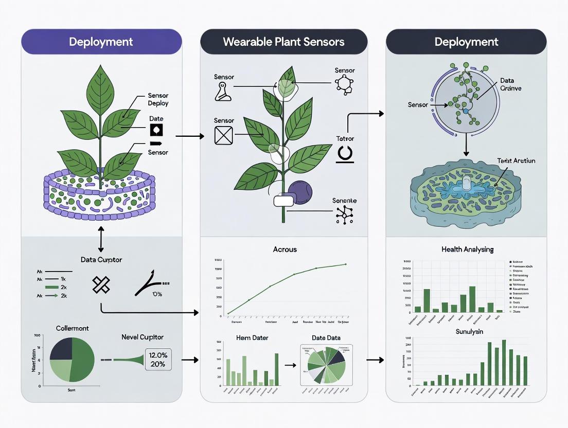
The effective deployment of wearable sensor networks for crop health monitoring follows a systematic workflow that integrates sensor data with analytical frameworks. The process begins with sensor selection and deployment based on specific monitoring objectives, followed by continuous data collection, multidimensional analysis, and finally actionable agricultural interventions.
Diagram 1: Sensor Deployment Workflow
This implementation framework highlights the continuous feedback loop enabled by wearable sensor technology. The machine learning analysis component is particularly crucial, as it enables quantitative differentiation between healthy and stressed plants and identifies optimal sensor combinations for specific monitoring scenarios [3]. This data-driven approach facilitates precise interventions that address specific plant health issues while minimizing resource inputs.
Effective data management is essential for leveraging the full potential of wearable sensor networks. As highlighted in data management guidelines for plant operations, proper handling of sensor data involves establishing standardized collection protocols, implementing quality control measures, and ensuring secure storage of time-series datasets [5]. The volume and velocity of data generated by continuous monitoring systems necessitate robust computational infrastructure and analytical pipelines to transform raw sensor readings into actionable agricultural intelligence.
Wearable plant sensors represent a transformative technology for addressing the urgent global challenges of food security and crop losses. By enabling non-invasive, continuous monitoring of plant health status, these sensors provide unprecedented insights into plant physiology and stress responses, facilitating early intervention strategies that can prevent yield losses [1] [2]. The integration of sustainable materials in sensor fabrication further enhances their potential for widespread deployment in precision agriculture systems [1].
Future advancements in wearable sensor technology will likely focus on several key areas: enhancing wireless power supply systems to enable long-term deployment, developing more sophisticated biodegradable substrates to reduce environmental impact, creating expanded agricultural sensor networks for field-scale monitoring, and refining machine learning algorithms for improved predictive capabilities [4]. As these technologies mature, wearable sensors are poised to become integral components of smart agricultural systems, helping to optimize crop productivity while minimizing environmental impacts—a critical dual objective for sustainable global food production.
Wearable plant sensors represent a transformative technological advancement in precision agriculture, evolving from rigid, invasive probes to sophisticated flexible, non-invasive platforms for real-time plant health monitoring. These devices enable in-situ, continuous tracking of physiological biomarkers and environmental parameters, providing unprecedented insights into plant growth, stress responses, and microclimate conditions. This evolution addresses critical limitations of traditional monitoring approaches, including biological incompatibility, limited temporal resolution, and potential tissue damage. By leveraging novel materials, sensing mechanisms, and integration strategies, modern wearable plant sensors offer enhanced biocompatibility, mechanical matching with plant tissues, and multifunctional monitoring capabilities. This article delineates the fundamental principles, material foundations, and operational frameworks governing these sensors, providing detailed application notes and experimental protocols to facilitate their effective deployment in agricultural research and practice, ultimately contributing to optimized crop management and improved global food security.
The monitoring of plant health has undergone a significant transformation, shifting from destructive sampling and laboratory analysis to non-invasive, continuous field monitoring. Traditional plant sensors primarily utilized rigid mechanical structures that required physical clamping or attachment to plant organs [4]. While providing valuable data, these early designs often induced biological rejection and caused damage to plant tissues during long-term contact, ultimately triggering the plant's self-healing mechanisms and potentially distorting collected data [4] [6]. Furthermore, non-contact methods such as optical imaging and remote sensing, while minimizing physical interference, often suffered from limitations in temporal resolution, susceptibility to environmental variables, and an inherent inability to directly measure internal physiological processes [4].
The emergence of flexible electronics has catalyzed a paradigm shift in plant sensor design [4] [6]. Flexible wearable sensors are electronic devices fabricated from compliant materials, characterized by their high flexibility, ductility, and ability to conform to the irregular, soft surfaces of plant organs such as leaves, stems, and fruits [4]. Their mechanical properties can be engineered to closely match those of plant tissues, enabling seamless integration without additional rigid mechanical fixtures [4]. This compatibility facilitates long-term, continuous monitoring of plant physiological information and the immediately surrounding microenvironment, providing more authentic and intuitive data feedback for agricultural management decisions [4] [7]. The core advantage of these platforms lies in their ability to perform real-time, in-situ monitoring of specific physiological biomarkers correlated with plant health, performance, and phenotyping, thereby bridging critical technological gaps in signal conditioning, processing, and wireless transmission [7].
Classification and Fundamental Operating Principles
Wearable plant sensors can be systematically categorized based on their sensing mechanism and the type of physiological or environmental parameter they measure. Understanding these fundamental operating principles is essential for selecting the appropriate sensor for a given research application.
Classification by Sensing Mechanism
Table 1: Classification of Wearable Plant Sensors by Sensing Mechanism
| Sensing Mechanism | Measured Parameter | Working Principle | Typical Applications in Plant Science |
|---|---|---|---|
| Resistive | Electrical Resistance | Converts mechanical stress (strain) or chemical interactions into changes in electrical resistance [8]. | Monitoring stem or fruit growth (strain), detection of specific gases (VOCs) [8]. |
| Capacitive | Capacitance | Utilizes a parallel-plate capacitor structure; mechanical signals or humidity changes alter the capacitance (C=ε₀εrA/d) [8]. | Humidity sensing on leaf surfaces, pressure measurement [8] [9]. |
| Piezoelectric | Voltage/Charge | Certain materials generate an electrical charge in response to applied mechanical stress due to a non-centrosymmetric crystal structure [8]. | Detection of wind-induced strain, growth-induced pressure. |
| Triboelectric | Voltage/Current | Converts mechanical movement into electrical energy via the coupling effect of triboelectrification and electrostatic induction [7] [8]. | Energy harvesting from plant movement, growth monitoring [7]. |
Classification by Target Analyte and Function
Based on their primary function and target, wearable plant sensors are broadly classified into three groups:
- Plant Growth Monitoring Sensors: These focus on detecting physical growth variables. For example, wearable strain sensors can measure the growth of stems or fruits by tracking minute dimensional changes [7].
- Plant Microclimate Monitoring Sensors: These are dedicated to monitoring environmental factors immediately surrounding the plant, such as humidity, temperature, and light intensity on the leaf surface [7].
- Plant Stress Detection Sensors: This group addresses biotic and abiotic stresses by profiling specific biomarkers, such as volatile organic compounds (VOCs) emitted during pathogen attack or reactive oxygen species generated under salinity stress [7] [3].
The following diagram illustrates the logical relationships between sensor types, their operating principles, and their final applications in plant health monitoring.
Material Foundations and Structural Design
The performance and biocompatibility of wearable plant sensors are fundamentally determined by their material composition and structural design. A typical sensor features a three-layer sandwich structure [7].
Core Components and Material Selection
Table 2: Core Components and Materials for Wearable Plant Sensors
| Component | Function | Common Material Choices | Key Properties |
|---|---|---|---|
| Flexible Substrate | Provides mechanical support and flexibility; interfaces directly with the plant. | Polydimethylsiloxane (PDMS) [9], Polyimide (PI) [7], Ecoflex [7], Hydrogels [7], Buna-N rubber [7]. | Biocompatibility, flexibility, low Young's modulus, waterproofing, gas permeability. |
| Sensing Element/ Electrode | Transduces a physiological or environmental signal into an electrical signal. | Graphene Oxide (GO) [9], Carbon Nanotubes (CNT) [7], Reduced Graphene Oxide (rGO) [7], Gold/Pt thin films [7] [9], Conductive inks [9], MXenes [7]. | High sensitivity, selectivity, electrical conductivity, stability under variable humidity/temperature. |
| Encapsulation Layer | Protects the sensing element from the external environment and secures the sensor to the plant. | PDMS [7], SU-8 [7], Ecoflex [7], self-adhesive porous breathable films [9]. | Biocompatibility, mechanical protection, environmental isolation, vapor permeability. |
The Scientist's Toolkit: Key Research Reagent Solutions
The fabrication of high-performance wearable sensors relies on a suite of specialized materials and reagents. The following table details essential items and their functions in sensor development.
Table 3: Essential Research Reagents and Materials for Sensor Fabrication
| Reagent/Material | Function/Application | Key Characteristics |
|---|---|---|
| PDMS (Sylgard 184) | Flexible substrate and encapsulation material [9]. | High optical clarity, biocompatibility, flexibility, tunable modulus. |
| Graphene Oxide (GO) | Humidity-sensing material [9]. | Abundant oxygen-containing functional groups for water molecule adsorption. |
| Sodium Dodecyl Sulfate (SDS) | Surfactant to improve dispersion of nanomaterials in polymer matrices [9]. | Enhances homogeneity of GO in PDMS. |
| Conductive Ink (e.g., JELCON CH-8) | Forming flexible interdigitated electrodes [9]. | High conductivity, adhesion to flexible substrates, mechanical stability. |
| Platinum Thin Film (e.g., PT1000) | Temperature-sensing element [9]. | Stable and linear resistance-temperature response. |
| Reduced Graphene Oxide (rGO) | Chemiresistive sensing of volatile organic compounds (VOCs) [7]. | Can be functionalized with ligands for specific gas detection. |
| Gold-coated Silver Nanowires (Au@AgNWs) | Electrodes for VOC sensors with high environmental stability [3]. | High stability against humidity and solvent exposure. |
Performance Metrics and Quantitative Analysis
Evaluating sensor performance requires a standardized set of quantitative metrics. The table below summarizes performance data from recent research, providing benchmarks for sensor development.
Table 4: Performance Metrics of Representative Wearable Plant Sensors
| Sensor Type | Sensing Material | Target Parameter | Sensitivity | Stability / Response Time | Reference Application |
|---|---|---|---|---|---|
| Humidity Sensor | Graphene Oxide (GO) on PDMS-GO-SDS | Leaf Surface Humidity | 4456 pF/% RH [9] | High stability over 21 days [7] | Tomato plant transpiration monitoring [9] |
| Temperature Sensor | Platinum Thin Film (PT1000) | Leaf Surface Temperature | ~3.93 Ω/°C [9] | N/A | Calculated VPD for transpiration intensity [9] |
| Strain Sensor | Graphene on Ecoflex | Fruit Growth | 3.9 / 2.9 kΩ/mm [7] | Stable for 336 hours (14 days) [7] | Monitoring fruit growth [7] |
| Humidity Sensor | Graphene Oxide (GO) on PI | Plant Water Status | 7945 Ω/% RH [7] | Stable for 21 days [7] | Plant water status monitoring [7] |
| VOC Sensor | Functionalized rGO | Plant Volatiles | Competitive with GC-MS [7] | Rapid, real-time detection [7] | Early disease and stress detection [7] [3] |
Detailed Experimental Protocols
Protocol 1: Fabrication of a Flexible Wearable Sensor for Leaf Transpiration Monitoring
This protocol details the fabrication of a multimodal sensor for in-situ detection of leaf surface temperature, humidity, and environmental temperature, enabling the calculation of Vapor Pressure Deficit (VPDL) as a measure of transpiration intensity [9].
I. Materials and Equipment
- Chemicals: PDMS sol and curing agent (e.g., Sylgard 184), Graphene Oxide (GO) aqueous solution (2 mg/mL), Monolayer graphene oxide powder, Sodium dodecyl sulfate (SDS) powder, Conductive ink (e.g., JELCON CH-8), Platinum thin film (e.g., PT1000).
- Equipment: Water bath ultrasonic cleaner, Magnetic stirrer, Precision electronic balance, Laser engraving machine, Constant temperature and humidity chamber, LCR tester, Screen printing setup.
II. Step-by-Step Procedure
Preparation of PDMS-GO-SDS Flexible Substrate: a. Prepare a GO-SDS mixed aqueous solution by ultrasonically dispersing monolayer GO powder and SDS powder (0.2 M final concentration) in ultrapure water. b. Mix PDMS sol and curing agent in a 10:1 (v/v) ratio in a beaker and stir thoroughly. c. Add the GO-SDS aqueous solution to the PDMS mixture (aqueous solution volume is 1/5 of PDMS volume) and stir until a uniform grayish-white mixture is obtained. d. Place the beaker in a vacuum chamber to remove air bubbles. e. Pour the mixture into a custom mold, level the surface with a scraper, and cure in an oven at 80°C for 2 hours.
Fabrication of Flexible Interdigitated Electrodes: a. Design an interdigitated electrode pattern using CAD software. b. Transfer the design to a laser engraving machine to create a screen printing template. c. Use screen printing to deposit conductive ink onto the cured PDMS-GO-SDS substrate, forming the electrodes. Air dry.
Modification of Sensing Elements: a. Humidity-Sensing Element: Pipette 100 μL of a 2 mg/mL GO aqueous solution onto the interdigitated electrode area and allow it to air dry. b. Temperature-Sensing Element: Attach a platinum thin film to a predefined position on the substrate using a small amount of uncured PDMS as an adhesive. Cure at 50°C for 2 hours.
Sensor Integration and Encapsulation: a. Integrate the humidity and temperature sensing elements on the front side (leaf-contacting side) of the substrate. b. Apply a localized self-adhesive, porous breathable film to the edges of the sensor for attachment to the leaf, ensuring the sensing elements remain exposed to the leaf microenvironment.
III. Calibration and Performance Validation
- Humidity Calibration: Place the sensor in a constant temperature and humidity chamber. Cycle the relative humidity from 20% to 90% RH while measuring the capacitance of the interdigitated electrode with an LCR meter to establish a calibration curve [9].
- Temperature Calibration: Similarly, vary the chamber temperature and measure the resistance of the platinum film to establish the resistance-temperature relationship.
IV. Deployment and Data Acquisition
- Gently attach the sensor to the abaxial side of a plant leaf using the integrated adhesive film.
- Connect the sensor to a portable data acquisition system or a wireless transmitter for continuous monitoring of capacitance (humidity) and resistance (temperature).
- Calculate VPDL in real-time using the acquired leaf surface temperature and humidity data.
Protocol 2: Deployment of a Multimodal Sensor Patch for Plant Stress Detection
This protocol outlines the procedure for using a sensor patch incorporating VOC, temperature, and humidity sensors to detect early signs of biotic and abiotic stress in plants [3].
I. Sensor Platform Preparation
- Acquire or fabricate a multimodal sensor patch that includes:
II. Baseline Data Collection
- Attach the sensor patch to a healthy plant (e.g., tomato plant) in a controlled growth chamber.
- Monitor and record the baseline signals from all sensor channels (VOC, temperature, humidity) for a minimum of 24-48 hours to establish the plant's healthy profile.
III. Stress Induction and Monitoring
- For Abiotic Stress: Subject the plant to a stress condition such as drought (withhold water), salinity (add NaCl to irrigation water), or light stress (prolonged darkness).
- For Biotic Stress: Inoculate the plant with a pathogen (e.g., Alternaria linariae for early blight) [3].
- Continuously monitor the sensor signals throughout the stress induction period. The unsupervised machine learning framework integrated with the sensor platform will begin processing the real-time data to identify deviations from the healthy baseline [3].
IV. Data Analysis and Interpretation
- The machine learning algorithm will quantitatively differentiate stressed plants from healthy controls and identify the most informative sensor combinations for a specific stressor [3].
- Compare the time of sensor-based stress detection with the onset of visible symptoms or traditional molecular diagnostic results to validate early detection capability.
The workflow for this stress detection protocol, from sensor preparation to data interpretation, is summarized below.
Wearable plant sensors have unequivocally evolved from simple rigid probes into sophisticated, flexible, non-invasive platforms capable of providing a holistic view of plant health. This transition is underpinned by advances in materials science, particularly the adoption of flexible substrates like PDMS and hydrogels, and sensitive elements such as graphene oxide and functionalized nanomaterials. The provided application notes and detailed protocols for monitoring transpiration via VPDL and detecting early stress through multimodal sensing offer researchers a practical framework for implementing this technology.
The future trajectory of wearable plant sensors points toward greater integration, intelligence, and sustainability. Key areas of development will include the creation of wireless, self-powered systems using energy harvesting techniques (e.g., triboelectric nanogenerators), the expansion of agricultural sensor networks within the Internet of Things (IoT) paradigm, and the deeper application of machine learning for predictive analytics and decision support in smart farming [10]. Furthermore, addressing the remaining challenges of long-term field stability, scalable manufacturing, and environmental impact through the development of biodegradable sensor materials will be critical for the widespread adoption and sustainable deployment of these transformative technologies in global agriculture [4] [10].
The deployment of wearable sensors for plant health monitoring represents a paradigm shift in precision agriculture, enabling real-time, in-situ acquisition of physiological and environmental data [2]. The core functionality of these devices hinges on three integral components arranged in a layered, sandwich-like structure: a flexible substrate that interfaces with the plant organ, a sensing element that transduces a biological or environmental signal into an electrical one, and an encapsulation material that protects the device from the environment [7]. The harmonious integration of these components determines not only the sensor's performance—its sensitivity, stability, and durability—but also its biocompatibility and long-term viability on the plant [8] [4]. This application note details the materials, functions, and experimental protocols related to these core components, providing a foundational guide for researchers developing next-generation plant wearables.
Core Components and Material Selection
The selection of materials for each core component is critical to ensure mechanical compliance with delicate plant tissues, minimal impact on plant growth, and reliable operation under harsh field conditions.
Flexible Substrates
The substrate serves as the mechanical backbone of the sensor, providing a platform for the sensing element while enabling intimate, non-damaging contact with stems, leaves, or fruits [7] [4].
- Function: To offer physical support and flexibility for conformal attachment to irregular plant surfaces without imposing mechanical stress or hindering growth.
- Key Materials:
- Polydimethylsiloxane (PDMS): A widely used silicone elastomer known for its biocompatibility, transparency, and stretchability. Its low surface energy is exploited for transferring other materials, such as laser-induced graphene [11].
- Ecoflex: A family of silicone rubbers that are exceptionally soft and stretchable, often used to achieve extreme flexibility and robust encapsulation [12] [11].
- Polyimide (PI): Valued for its excellent thermal stability and mechanical strength, often used in applications requiring robust but thin film substrates [7] [8].
- Hydrogels: Networks of cross-linked polymers with high water content; their tissue-like mechanical properties and potential for ion conductivity make them suitable for highly biocompatible interfaces [7].
Sensing Elements
The sensing element is the active component responsible for detecting stimuli and converting them into measurable electrical signals. Its design is dictated by the target parameter (e.g., strain, vapor, or chemicals) [2] [8].
- Function: To transduce physiological or environmental cues (e.g., strain, humidity, volatile organic compounds) into quantifiable electrical signals such as changes in resistance, capacitance, or voltage.
- Key Materials and Mechanisms:
- Piezoresistive Materials: These materials change electrical resistance upon mechanical deformation. Common examples include:
- Laser-Induced Graphene (LIG): A porous, conductive carbon material directly patterned onto polymer substrates using a laser, enabling complex and sensitive strain-sensing structures [11].
- Carbon Nanotubes (CNTs)/Graphite: Dispersed in inks or composites to form conductive networks whose resistance changes with strain [7] [13].
- Conductive Textiles: Flexible textiles coated with conductive materials, used for creating wearable strain sensors for stems and fruits [12].
- Capacitive Elements: Typically composed of two flexible electrodes separated by a dielectric layer. Changes in the distance between electrodes or the dielectric constant of the separating layer (e.g., due to humidity) result in a measurable capacitance change [8].
- Functionalized Nanomaterials: Used in chemical sensing. For instance, reduced Graphene Oxide (rGO) functionalized with specific ligands can selectively bind with volatile organic compounds, altering its resistance [7].
- Piezoresistive Materials: These materials change electrical resistance upon mechanical deformation. Common examples include:
Encapsulation Materials
The encapsulation layer seals and protects the sensing element from environmental damage, such as moisture, dust, and mechanical abrasion, while also ensuring the device does not adversely affect the plant [7].
- Function: To provide a barrier against environmental factors (rain, soil, UV radiation) and insulate the sensing element, thereby enhancing the sensor's longevity and signal stability.
- Key Materials:
- PDMS and Ecoflex: These elastomers are again the materials of choice for encapsulation due to their flexibility, waterproof nature, and robustness, forming a fully flexible and protected sandwich structure [7] [11].
- SU-8: A high-contrast, epoxy-based photoresist used to create robust, patterned insulating layers on sensors [7].
- Layered Silicone Structures: For applications in outdoor fields, sensors can be encapsulated within a multi-layer structure of silicone polymers (e.g., multiple casts of Ecoflex) to provide superior environmental isolation [12].
Table 1: Quantitative Performance of Sensor Components from Representative Studies
| Sensor Function | Sensing Element | Substrate/Encapsulation | Key Performance Metric | Stability/Durability | Application (Plant Organ) | Reference |
|---|---|---|---|---|---|---|
| Plant Growth (Strain) | Deposited Graphite Ink | Buna-N Rubber | Strain range: 1% to 8% | 30 minutes | Stem | [7] |
| Plant Growth (Strain) | CNT/Graphite | Latex | - | 7 days | Stem | [7] |
| Plant Pulse (Strain) | Laser-Induced Graphene (LIG) | Ecoflex (Sandwich) | Temp. resistance coefficient: 0.17/°C | - | Stem | [11] |
| Fruit Growth (Strain) | Graphene | PDMS & Ecoflex | Sensitivity: 3.9/2.9 kΩ/mm | 336 hours (14 days) | Fruit | [7] |
| Microclimate (Humidity) | Graphene Oxide (GO) | Polyimide (PI) | Sensitivity: 7945 Ω/% RH | 21 days | Leaf Surface | [7] |
| High-Throughput Phenotyping | Carbonized Silk Georgette | Elastomer Film | Detection limit: 0.03%–0.17% strain | Season-long | Stem & Fruit | [13] |
Experimental Protocols
Protocol: Fabrication of a Biomimetic Adaptive Winding Strain (AWS) Sensor
This protocol outlines the procedure for creating a tendril-inspired sensor for monitoring stem diameter variations (plant pulse), based on the work of [11].
1. Preparation of Laser-Induced Graphene (LIG) Pattern:
- Materials: Phenolic resin (PR) film or Polyimide (PI) film; CO₂ infrared laser system.
- Procedure:
- Place the PR or PI film on the laser bed.
- Use computer-controlled software to define a serpentine pattern for the sensing element.
- Irradiate the film with a laser under optimized parameters (e.g., power 2.5 W, scanning rate 27 cm/s) to convert the irradiated areas into 3D porous graphene.
- Verify the quality of the LIG using Scanning Electron Microscopy (SEM) and Raman spectroscopy (ID/IG ratio ~0.52 indicates highly crystalline graphene).
2. Transfer of LIG to Elastomeric Substrate:
- Materials: PDMS slab, Ecoflex precursor.
- Procedure:
- Cast a layer of Ecoflex precursor onto the LIG/PDMS substrate.
- Cure the Ecoflex according to the manufacturer's specifications (e.g., at room temperature for 4 hours).
- Peel off the cured Ecoflex, thereby completely transferring the patterned LIG from the low-surface-energy PDMS to the Ecoflex film.
3. Formation of Tendril-like Structure:
- Materials: Prestretched Ecoflex film.
- Procedure:
- Prestretch a separate Ecoflex film to a predetermined strain (e.g., 30% to 200%).
- Attach the LIG-transferred Ecoflex from Step 2 onto the prestretched Ecoflex film.
- Carefully release the prestrain. The mismatched strain between the two layers will cause the composite film to automatically curl into a stable, tendril-like spiral structure.
4. Encapsulation and Integration:
- Materials: Additional Ecoflex precursor.
- Procedure:
- Apply a final, thin layer of Ecoflex over the sensor to fully encapsulate the LIG sensing element, forming a protective sandwich structure (Ecoflex-LIG-Ecoflex).
- Connect the sensor to a flexible printed circuit board with a WiFi module for wireless data transmission.
Protocol: Characterization of a Flexible Strain Sensor
1. Electromechanical Characterization:
- Equipment: Universal mechanical testing system, source meter (e.g., Keithley 2450).
- Procedure:
- Mount the sensor on the mechanical tester and connect its electrodes to the source meter.
- Subject the sensor to controlled tensile strain cycles (e.g., from 0% to 50% strain) while simultaneously recording the change in electrical resistance (ΔR/R₀).
- Plot the gauge factor (GF), calculated as (ΔR/R₀)/ε, where ε is the applied strain.
- Perform cyclic stability tests (e.g., 10,000 cycles at 100% strain) to assess durability [13].
2. Environmental Stability Testing:
- Equipment: Environmental chamber, data acquisition system.
- Procedure:
- Place the sensor inside an environmental chamber.
- Subject it to varying conditions of temperature (e.g., 10°C to 50°C) and relative humidity (e.g., 20% to 90% RH) while monitoring the baseline signal drift.
- For field testing, deploy the sensor on a plant organ and collect data continuously over days or weeks to evaluate long-term performance and robustness against rain, wind, and UV exposure [13].
3. Biocompatibility Assessment:
- Procedure:
- Install the sensor on the target plant organ (e.g., stem, fruit).
- Monitor the plant over the sensor's deployment period for any visible signs of stress, damage, or growth inhibition at the attachment site.
- Compare the growth rate of the engineered organ with a control plant without a sensor.
The Scientist's Toolkit: Research Reagent Solutions
Table 2: Essential Materials for Plant Wearable Sensor Development
| Item/Category | Example Specifics | Primary Function in Research |
|---|---|---|
| Elastomeric Substrates | PDMS (Sylgard 184), Ecoflex 00-30 | Serve as flexible, stretchable, and biocompatible matrices for sensor fabrication and encapsulation. |
| Conductive Nanomaterials | Laser-Induced Graphene (LIG), Carbon Nanotubes (CNTs), Reduced Graphene Oxide (rGO) | Act as the active sensing element for detecting strain, chemicals, or humidity. |
| Functionalization Agents | Ligands for specific VOC detection (e.g., for ethylene) | Impart chemical selectivity to nanosensors for detecting specific plant volatiles or biomarkers. |
| Conductive Inks & Textiles | Graphite-based inks, Eeontex conductive textile | Enable the creation of flexible electrodes and strain gauges via writing or cutting methods. |
| Characterization Equipment | SEM, Raman Spectrometer, Universal Mechanical Tester | Used for material characterization (morphology, structure) and electromechanical performance validation. |
Schematic Diagrams
Diagram 1: Wearable plant sensor architecture and signal flow.
Diagram 2: Fabrication workflow for biomimetic sensors.
Wearable plant sensors represent a transformative technology in precision agriculture, enabling non-invasive, real-time monitoring of plant physiological and environmental status [2]. These flexible, miniaturized devices attach directly to various plant parts—such as stems, leaves, and fruits—providing continuous data streams that reflect plant health [1]. The deployment of these sensors facilitates data-driven decision-making for crop management, allowing for early detection of stress, optimized resource allocation, and ultimately, enhanced agricultural productivity [14]. Within the framework of a broader thesis on plant health monitoring research, this document provides detailed application notes and experimental protocols for the three primary sensor classifications: physical, chemical, and electrophysiological.
Sensor Classification and Operating Principles
Wearable plant sensors are categorized based on the type of signals they detect and their underlying sensing mechanisms. The primary classifications are physical, chemical, and electrophysiological sensors [2] [14]. The table below summarizes the core principles, target parameters, and common transducer materials for each category.
Table 1: Classification and Operating Principles of Wearable Plant Sensors
| Sensor Category | Measurable Parameters | Sensing Mechanism | Common Transducer Materials/Designs |
|---|---|---|---|
| Physical Sensors | Strain, Temperature, Humidity, Light [2] | Capacitive, Piezoresistive, Piezoelectric [8] | Parallel-plate capacitors (strain, humidity); Thermistors (temperature); Photodetectors (light) [8] |
| Chemical Sensors | Volatile Organic Compounds (VOCs), Reactive Oxygen Species (ROS), Ions, Pigments, Pesticides [2] [1] | Resistive (Semiconductor), Electrochemical [8] | Metal oxide semiconductors (e.g., for VOCs); Functionalized electrodes (e.g., for ions, pesticides) [8] |
| Electrophysiological Sensors | Action Potentials, Variation Potentials [2] | Potentiometric | High-impedance electrodes (e.g., Ag/AgCl) [15] |
Physical Sensors
Physical sensors monitor mechanical and environmental variables. Piezoresistive strain sensors are widely used; their resistance (R) changes with mechanical deformation, governed by ( R = \rho L/S ), where ( \rho ) is resistivity, L is length, and S is cross-sectional area [8]. This principle allows monitoring of plant growth and micro-movements. Capacitive sensors are often employed for humidity and pressure sensing, where the capacitance ( C = \varepsilon0 \varepsilonr A/d ) changes with the dielectric constant (εr) due to water vapor absorption or with the distance (d) between electrodes under pressure [8].
Chemical Sensors
Chemical sensors detect specific molecules and ions. Resistive semiconductor gas sensors rely on the adsorption of gas molecules (e.g., VOCs) onto metal oxide surfaces, which alters the material's electrical resistance by changing charge carrier concentration [8]. For instance, in an n-type semiconductor, oxidizing gases remove electrons, increasing resistance. Electrochemical sensors involve redox reactions between the target analyte and an electrolyte at a working electrode, generating a measurable change in current or potential for detecting specific ions or pesticides [8].
Electrophysiological Sensors
These sensors measure electrical potential differences generated by plants. They operate on a potentiometric principle, using high-impedance electrodes to capture small voltage fluctuations (action and variation potentials) in plant tissues that signal physiological responses to stressors [15]. Proper electrode placement and impedance matching are critical for obtaining stable signals [15].
Application Notes: Experimental Protocols
Protocol for Deploying Electrophysiological Sensors to Detect Spider Mite Infestation
This protocol details a methodology for detecting biotic stress (spider mite infestation) in tomato plants using electrophysiological sensors, based on a published study [15].
3.1.1 Research Reagent Solutions & Essential Materials Table 2: Key Materials for Electrophysiological Monitoring
| Item Name | Function/Description | Specifications/Notes |
|---|---|---|
| PhytlSigns Device [15] | Multi-channel electrophysiology signal recorder. | 8 electrode pairs, sampling rate: 500 Hz, high input impedance (order of MΩ). |
| Custom-Built Electrodes [15] | Signal acquisition from plant tissue. | 0.5 mm diameter silver-coated copper wire, coaxial cable. |
| Data Logger [15] | Monitor ambient conditions. | Records temperature and relative humidity. |
| Notch Filter [15] | Signal preprocessing. | Software or hardware filter at 50 Hz and 100 Hz to remove line noise. |
3.1.2 Step-by-Step Procedure
- Plant Preparation & Experimental Design: Use healthy, 50-day-old tomato plants (e.g., Solanum lycopersicum L. cv. Admiro). Establish a controlled environment (e.g., greenhouse) with recorded temperature and humidity. Divide plants into control and infested groups [15].
- Electrode Placement & Signal Stabilization:
- Insert the active electrode into the plant stem above the first floral bud.
- Insert the reference (ground) electrode into the stem below the first leaf.
- Ensure electrodes are inserted into the plant's conducting bundles for signal stability.
- Monitor the signal for the initial 72 hours, repositioning electrodes if instability is observed [15].
- Infestation & Data Acquisition:
- On "Day 0," inoculate plants in the infested group with ~30 mobile stages of Tetranychus urticae (spider mites). Leave control plants untreated.
- Continuously record electrophysiological signals from all plants (control and infested) for the duration of the experiment. For analysis, select specific data fragments (e.g., 2 days pre-infestation and 2 days post-infestation before treatment) [15].
- Signal Preprocessing:
- Apply a notch filter to the raw signal to remove 50 Hz and 100 Hz electrical noise [15].
- Segment the continuous data stream into samples for feature extraction.
3.1.3 Data Analysis and Machine Learning Classification
- Feature Extraction: From the preprocessed signal samples, extract time-domain and frequency-domain features. The Hjorth complexity parameter has been shown to contain highly relevant information for discriminating plant stress induced by spider mites [15].
- Model Training: Employ a supervised machine learning algorithm, such as the Gradient Boosted Tree algorithm. Train the model using a reduced set of features on a labeled dataset (samples from pre-infestation "normal" state and post-infestation "stressed" state) [15].
- Performance: The classification model can achieve an accuracy of approximately 80% in identifying the plant's stressed state when using signal samples recorded during daylight [15].
Protocol for Fabrication and Deployment of a Resistive Strain Sensor
This protocol outlines the steps for creating and using a simple, flexible resistive strain sensor to monitor plant stem micro-movements.
3.2.1 Materials
- Flexible Substrate: Eco-friendly polymer (e.g., Polylactic Acid - PLA) or traditional flexible polymer (e.g., PDMS) [1].
- Conductive Material: Carbon-based ink (e.g., carbon black, graphene) or a conductive composite [8].
- Fabrication Tool: Inkjet printer or direct writing tool for patterning the conductive material on the substrate [1].
3.2.2 Step-by-Step Procedure
- Substrate Preparation: Prepare a flexible, biodegradable substrate such as a PLA film [1].
- Sensor Patterning: Deposit the conductive carbon-based ink onto the substrate in a meandering pattern to enhance strain sensitivity. Techniques like inkjet printing or direct writing can be used [1].
- Curing: Cure the printed sensor according to the specifications of the conductive ink (e.g., thermal curing).
- Attachment & Calibration: Attach the cured sensor securely to the plant stem using a biocompatible adhesive. Calibrate the sensor by relating changes in electrical resistance (ΔR/R₀) to known levels of mechanical strain.
- Data Acquisition: Connect the sensor to a data acquisition system (e.g., a digital multimeter with logging capabilities or a custom wireless node) to continuously monitor resistance.
The Scientist's Toolkit: Essential Materials and Reagents
Successful deployment of a wearable plant sensor system requires a suite of specialized materials and reagents. The following table expands on the core items needed for sensor fabrication and deployment.
Table 3: Research Reagent Solutions for Wearable Plant Sensor Development
| Category/Item | Function/Description | Application Notes |
|---|---|---|
| Flexible Substrates | Provides a flexible, supportive base for the sensor. | Biodegradable polymers (PLA, cellulose) are preferred for sustainability [1]. |
| Conductive Materials | Forms the sensing element or electrodes. | Carbon nanomaterials (graphene, CB) offer high conductivity and sensitivity [1]. |
| Fabrication Techniques | Methods for patterning and manufacturing sensors. | Rapid techniques like 3D printing and inkjet printing reduce waste [1]. |
| Signal Acquisition System | Hardware to read and record sensor signals. | Multi-channel devices (e.g., PhytlSigns) are needed for electrophysiology [15]. |
| Data Analysis Software | For processing signals and machine learning. | Custom scripts (e.g., Python/MATLAB) for feature extraction and classification [15]. |
The classification of wearable plant sensors into physical, chemical, and electrophysiological types provides a structured framework for monitoring plant health. The experimental protocols outlined here offer researchers a foundation for deploying these sensors to detect critical stressors like pest infestations. Future development in this field will focus on enhancing sensor sensitivity, reliability, and stability under field conditions [8]. Key challenges include ensuring robust attachment to complex plant surfaces, minimizing the impact on plant physiology, and developing fully biodegradable sensor systems from sustainable materials to reduce electronic waste [1]. The integration of wearable sensor data with AI, IoT, and cloud computing will further revolutionize precision agriculture, enabling fully automated, data-driven farming systems [1].
The deployment of wearable sensors is revolutionizing plant health monitoring research by enabling the real-time, in-situ acquisition of physiological and environmental data. These sensors provide researchers and drug development professionals with critical insights into plant growth, stress responses, and microclimate conditions, which are paramount for advancing precision agriculture and safeguarding crop productivity [7]. The operational core of these devices lies in their sensing mechanisms, primarily resistive, capacitive, and piezoelectric principles, which transduce physical and chemical stimuli into quantifiable electrical signals. This document provides detailed application notes and experimental protocols for these key sensing principles, framed within the context of a broader thesis on wearable plant sensors.
Fundamental Sensing Mechanisms
Working Principles and Theoretical Foundations
Wearable sensors for plants convert specific biological or environmental parameters into measurable electrical signals through various transduction mechanisms. The selection of a sensing principle is dictated by the target analyte, required sensitivity, and the specific application scenario in plant health monitoring [8].
Table 1: Comparison of Key Sensing Mechanisms for Wearable Plant Sensors
| Sensing Mechanism | Measured Quantity | Primary Application in Plant Monitoring | Key Advantages | Inherent Challenges |
|---|---|---|---|---|
| Resistive | Change in Electrical Resistance (R) | Strain (growth, movement), Gas concentration (VOCs) | Simple readout, high sensitivity for strain, wide material options | Sensitive to temperature, can exhibit signal drift and hysteresis [16] [8] |
| Capacitive | Change in Capacitance (C) | Strain (growth, movement), Humidity, Pressure | Low power consumption, stable for static measurements, insensitive to temperature | Susceptible to electromagnetic interference, can have parasitic capacitance [16] [8] |
| Piezoelectric | Generated Charge or Voltage | Dynamic strain (e.g., wind-induced leaf movement) | Self-powering capability, high sensitivity to dynamic events | Cannot measure static stimuli, sensitive to external vibrations [16] [8] |
The fundamental working principles are as follows:
Resistive Sensing: This mechanism relies on the change in electrical resistance of a material upon mechanical deformation or interaction with a target gas. For strain sensing, the resistance
Ris given byR = ρL/S, whereρis the resistivity,Lis the length, andSis the cross-sectional area of the conductive material. Stretching causesLto increase andSto decrease, leading to a measurable increase in resistance [8]. In gas sensing, the resistance changes due to charge transfer between the sensing material (e.g., a metal oxide or graphene) and gas molecules, altering the carrier concentration [8].Capacitive Sensing: These sensors typically function as parallel-plate capacitors. The capacitance
Cis calculated asC = ε₀εᵣA/d, whereε₀is the vacuum permittivity,εᵣis the relative dielectric constant of the material between the plates,Ais the overlapping area of the electrodes, anddis the distance between them [16] [8]. Mechanical strain can alterAandd, while changes in environmental humidity or the presence of certain gases can affectεᵣ, thereby modulating the capacitance.Piezoelectric Sensing: The mechanism is based on the piezoelectric effect, where certain non-centrosymmetric materials generate an electric charge in response to applied mechanical stress. This charge is proportional to the strain, allowing for the detection of dynamic mechanical events [8].
Figure 1: Logical workflow of sensor signal transduction from stimulus to electrical output via different sensing principles.
The Scientist's Toolkit: Research Reagent Solutions
The fabrication and performance of wearable plant sensors are critically dependent on the materials used. The table below catalogs essential materials and their functions as derived from recent research.
Table 2: Key Research Reagents and Materials for Wearable Plant Sensor Fabrication
| Material/Component | Function/Application | Key Properties & Rationale |
|---|---|---|
| Reduced Graphene Oxide (rGO) | Sensing element for VOC detection [7] [17] | High surface area; can be functionalized with ligands to enhance selectivity for specific plant VOCs. |
| Ag Ink | Conductive electrode for printed capacitive and resistive sensors [16] | High conductivity; suitable for direct ink writing (DIW) to create stretchable helical electrodes. |
| BTO@Ecoflex | Dielectric/encapsulation layer for capacitive sensors [16] | High dielectric property from Barium Titanate (BTO) enhances sensitivity; Ecoflex provides flexibility and biocompatibility. |
| TPU (Thermoplastic Polyurethane) | Flexible substrate for fiber-shaped sensors [16] | Excellent elasticity (>400% strain) and high rebound rate, providing a robust and stretchable base. |
| Metal Oxides (e.g., ZnO, SnO₂) | Sensing layer for semiconductor gas sensors [8] | Surface oxygen ion adsorption model enables detection of redox-active gases; high stability. |
| Polydimethylsiloxane (PDMS) | Flexible substrate and encapsulation material [7] [18] | Biocompatible, flexible, optically transparent, and easy to mold, making it ideal for various sensor designs. |
| ZnIn₂S₄ (ZIS) Nanosheets | Primary sensing medium for multimodal microclimate sensors [7] | Used in flexible sensors to assess health status by monitoring factors like humidity and temperature. |
Application Notes & Experimental Protocols
Protocol 1: Fabrication and Characterization of a Resistive VOC Sensor for Plant Stress
Objective: To fabricate a wearable, resistive gas sensor based on functionalized reduced Graphene Oxide (rGO) for real-time profiling of plant-emitted Volatile Organic Compounds (VOCs) as biomarkers of stress [7] [17].
Background: Plants release specific VOCs (e.g., methanol, terpenoids, hexenal) in response to biotic (pathogen attack) and abiotic (drought, salinity) stresses. This protocol details the creation of a chemiresistive sensor array for in-situ detection [17].
Materials:
- Sensing Material: Aqueous dispersion of Graphene Oxide (GO).
- Reducing Agent: L-Ascorbic acid or hydrazine hydrate.
- Ligands: Chloroauric acid, copper(II) chloride, or other metal salts for functionalization to enhance VOC selectivity [7].
- Substrate: Flexible polyimide tape.
- Electrodes: Interdigitated electrodes (IDEs) patterned via photolithography or screen-printed using gold or carbon ink.
- Equipment: Spin coater, chemical vapor deposition (CVD) system or solution bath for reduction, probe station, impedance analyzer or source meter unit (SMU).
Procedure:
- Substrate Preparation: Clean the polyimide substrate with isopropanol and deionized water in an ultrasonic bath. Dry under a stream of nitrogen gas.
- Electrode Patterning: Photolithographically define or screen-print interdigitated electrodes onto the substrate.
- rGO Synthesis & Functionalization:
- Drop-cast the GO dispersion onto the IDE area and spin-coat to form a thin film.
- Reduce the GO film to rGO by exposing it to hydrazine vapor in a sealed container at 80°C for 24 hours or via thermal annealing.
- For functionalization, immerse the rGO/IDE in a 1 mM solution of the chosen metal salt (e.g., HAuCl₄) for 1 hour, then rinse gently with DI water and dry.
- Sensor Encapsulation: Encapsulate the sensor with a porous membrane (e.g., PDMS) that allows VOC permeation while protecting the sensing layer from direct moisture and mechanical damage.
- Calibration and Testing:
- Place the sensor in a sealed gas chamber with controlled gas flow.
- Expose the sensor to calibrated concentrations of target VOCs (e.g., methanol, ethylene) in synthetic air (using mass flow controllers).
- Monitor the change in electrical resistance in real-time using an SMU.
- Generate a calibration curve of relative resistance change (ΔR/R₀) versus VOC concentration.
Figure 2: Experimental workflow for fabricating a resistive VOC sensor.
Protocol 2: Fabrication of a Dual-Mode Capacitive Strain Sensor via Direct Ink Writing
Objective: To fabricate a fiber-shaped flexible capacitive strain sensor (FSFCSS) using Direct Ink Writing (DIW) for simultaneous monitoring of axial tensile strain and radial expansion strain in plant stems or fruits [16].
Background: This sensor utilizes a parallel helical electrode structure printed on an elastic fiber. Axial strain changes the electrode overlap area A and distance d, while radial pressure (expansion) primarily changes d, both affecting capacitance C = ε₀εᵣA/d [16].
Materials:
- Substrate: Thermoplastic Polyurethane (TPU) fiber tube (e.g., 1.0 mm diameter).
- Conductive Ink: Stretchable silver nanoparticle ink.
- Dielectric/Encapsulation Ink: Mixture of Barium Titanate (BTO) nanoparticles and Ecoflex silicone elastomer.
- Fabrication Equipment: DIW 3D printer with pneumatic nozzle and a motorized fixture for rotating the fiber.
- Characterization Equipment: LCR meter for capacitance measurement, tensile testing stage.
Procedure:
- Substrate Pretreatment: Secure the TPU fiber in the motorized fixture of the DIW printer. Treat the fiber surface with oxygen plasma and a surfactant to achieve a hydrophilic surface for improved ink adhesion.
- Print Helical Electrodes:
- Program the printer for a parallel helical path along the fiber's long axis.
- Print the Ag ink onto the rotating TPU fiber using optimized pneumatic pressure (e.g., 25-40 psi) and print speed to achieve a continuous, uniform electrode line. Cure the ink as per manufacturer specifications (e.g., 80°C for 30 min).
- Apply Dielectric/Encapsulation Layer:
- Prepare the BTO@Ecoflex composite and load it into a DIW syringe.
- Print the dielectric layer directly over the helical electrodes, fully encapsulating them. Cure the Ecoflex at 60°C for 2 hours.
- Sensor Characterization:
- Axial Tensile Strain: Mount the FSFCSS on a tensile stage. Connect the sensor electrodes to an LCR meter. Apply uniaxial strain from 0% to a maximum (e.g., 180%) in increments. Record the capacitance
Cat each strain point. Calculate sensitivity as the gauge factorGF = (ΔC/C₀)/Δε. - Radial Expansion Strain: Use a calibrated pressure source to apply radial pressure to the sensor. Measure the corresponding capacitance change. Calculate sensitivity as
S = (ΔC/C₀)/ΔP.
- Axial Tensile Strain: Mount the FSFCSS on a tensile stage. Connect the sensor electrodes to an LCR meter. Apply uniaxial strain from 0% to a maximum (e.g., 180%) in increments. Record the capacitance
Table 3: Performance Metrics for a Representative DIW-fabricated Capacitive Strain Sensor [16]
| Performance Metric | Axial Tensile Mode | Radial Expansion Mode |
|---|---|---|
| Detection Range | 0% to 178% strain | N/A (Pressure dependent) |
| Sensitivity (Gauge Factor) | 0.924 | 0.00086 mmHg⁻¹ |
| Lowest Detection Limit | 0.6% strain | N/A |
| Hysteresis Coefficient | 1.44% | N/A |
| Mechanical Stability | Excellent performance over numerous cycles | Excellent responsiveness to dynamic pressure |
Sensing Mechanism Pathways for Gas and Strain Detection
The following diagrams illustrate the fundamental sensing pathways for gas and strain detection.
Figure 3: Resistive gas sensing pathway in n-type metal oxide semiconductors.
Figure 4: Capacitive sensing pathway for strain and microclimate detection.
From Lab to Field: Deployment Methodologies and Real-World Applications
The deployment of wearable sensors on plants represents a paradigm shift in precision agriculture and botanical research, enabling the real-time, in-situ monitoring of physiological status [19]. These sensors can be closely attached to the plant surface to monitor growth rates, leaf surface temperature and humidity, organic volatiles released, and electrophysiological signals [19]. However, a significant challenge persists in their application, particularly concerning the sensor-plant interface. The fundamental objectives are to ensure robust sensor attachment while maintaining plant biocompatibility—minimizing damage to plant tissues, avoiding the obstruction of natural processes like gas exchange, and reducing device interference on complex plant surfaces [19]. These challenges must be addressed to facilitate the reliable, long-term, and high-throughput monitoring necessary for advanced agricultural systems and research applications. This document outlines standardized protocols and material considerations to achieve these critical goals.
Research Reagent and Material Solutions
The selection of appropriate materials is the cornerstone of developing plant-wearable sensors that are both effective and minimally invasive. The following table details key materials and their specific functions in sensor fabrication and deployment.
Table 1: Essential Materials for Plant-Wearable Sensor Deployment
| Material Category | Specific Examples | Function and Rationale |
|---|---|---|
| Sensing Substrates | Carbonized silk georgette [20] | Serves as a strain-sensing material, offering an exceptional detection limit (0.03%–0.17% strain), high stretchability (tensile strain up to 100%), and remarkable durability for season-long use [20]. |
| Electrode Materials | Gold-coated silver nanowires (Au@AgNWs) [3] | Provides high electrical conductivity for sensing while demonstrating high stability against environmental factors like humidity and solvent exposure, ensuring consistent performance [3]. |
| Adhesives & Interfaces | Polydopamine-based coatings [21] | Mimics the adhesive properties of natural mussel filaments, providing strong, biocompatible adhesion to various plant surfaces in a humid environment without causing significant tissue damage [21]. |
| Functional Sensing Inks | VOC-sensing materials [3] | Enables the real-time detection of plant-emitted volatile organic compounds (VOCs), which are key early indicators of plant stress or pathogen infection [3]. |
| Encapsulation Layers | Undisclosed flexible polymers | Protects the sensitive electronic components from environmental damage (e.g., rain, dust) and minimizes the sensor's impact on the plant's microenvironment [19]. |
Quantitative Sensor Performance Metrics
Evaluating the performance of wearable plant sensors requires a standardized set of quantitative metrics. The data below, derived from recent advanced sensor systems, provides benchmarks for comparison and goal-setting in experimental design.
Table 2: Performance Metrics of Advanced Plant-Wearable Sensors
| Sensor System | Sensed Parameter(s) | Key Performance Metrics | Tested Plant Species |
|---|---|---|---|
| PlantRing [20] | Organ circumference (strain) | Detection Limit: 0.03%–0.17% strainStretchability: Up to 100% tensile strainDurability: Season-long use | Tomato, Watermelon, Soybean |
| Multimodal Patch [3] | VOCs, Temperature, Humidity | Early Disease Detection: Earlier than molecular methodsStability: Reliable under harsh conditionsSelectivity: Differentiates diseases and abiotic stresses | Tomato (for TSWV, Early Blight) |
| SERS Platform [21] | Biomarkers (e.g., α-Fetoprotein) | Limit of Detection (LOD): 16.73 ng/mLLinear Range: 0 - 500 ng/mL | [Note: Clinical sensor included for performance analogy] |
| THz SPR Biosensor [21] | Biochemical interactions | Phase Sensitivity: Up to 3.1x10⁵ deg/RIU (liquid) | [Note: Conceptual sensor for novel techniques] |
Experimental Protocol for Sensor Attachment and Validation
This protocol provides a detailed methodology for attaching a wearable sensor to a plant organ, such as a stem or fruit, and validating the attachment for minimal interference and long-term reliability.
Materials and Pre-attachment Preparation
- Sensor Device: PlantRing-style strain sensor or a multimodal sensor patch [20] [3].
- Adhesive: Biocompatible, water-resistant adhesive such as a polydopamine-based solution [21].
- Plant Material: Healthy, mature plants (e.g., tomato, soybean).
- Tools: Precision tweezers, microliter pipette, gloves, and a data acquisition system.
- Environmental Chamber: For controlling light, temperature, and humidity during testing.
Step-by-Step Attachment Procedure
- Surface Preparation: Gently clean the target attachment site (e.g., stem, fruit) on the plant with deionized water to remove dust and debris. Allow the surface to air-dry completely. Avoid using chemical solvents that may damage the plant cuticle.
- Adhesive Application: Using a pipette, apply a thin, uniform layer of the biocompatible adhesive to the back of the sensor substrate. The goal is to achieve full coverage without excess adhesive that could squeeze out and contact other plant tissues.
- Sensor Mounting: Using precision tweezers, carefully align the sensor with the prepared plant surface. Gently press the sensor into place, applying uniform pressure for 30-60 seconds to ensure proper initial bonding.
- Curing: Allow the adhesive to fully cure according to the manufacturer's specifications. This may involve waiting for a set period at ambient conditions.
- Connection and Calibration: Connect the sensor to the data acquisition system. Record a baseline measurement under stable environmental conditions to calibrate the system.
Validation and Interference Assessment
- Biocompatibility Check: Monitor the sensor attachment site daily for visual signs of stress or damage, such as necrosis, chlorosis (yellowing), or abnormal growth deformation over a period of one week [19].
- Gas Exchange Interference Test: Compare the photosynthetic and transpiration rates of an instrumented leaf with a control leaf on the same plant using a portable gas exchange system. A statistically insignificant difference (p > 0.05) indicates minimal interference.
- Mechanical Integrity Test: For strain sensors, verify the sensor remains firmly attached after subjecting the plant to gentle mechanical disturbance, such as simulated wind. The sensor output should return to baseline after the disturbance ceases, indicating a stable bond [20].
- Long-Term Durability Assessment: Continuously log data over a growing season. A functional sensor that maintains a stable baseline and shows no signs of physical degradation or attachment failure confirms long-term reliability [20].
Workflow and Signaling Pathways
The following diagram illustrates the logical workflow and decision-making process for selecting, deploying, and validating a sensor attachment strategy, ensuring biocompatibility and minimal interference.
Sensor Attachment and Validation Workflow
Data Management for FAIR Compliance
To ensure that the data generated from these sensor deployments is Findable, Accessible, Interoperable, and Reusable (FAIR), researchers should integrate structural metadata from the beginning of the data's life [22]. A recommended practice is to use the ODAM (Open Data for Access and Mining) approach, which structures experimental data tables in spreadsheets similarly to data dictionaries [22]. This includes:
- Structural Metadata: Describing links between data tables and providing unambiguous definitions for all columns.
- Semantic Annotation: Using links to community-approved ontologies to define the measured variables.
- Standardized Export: Converting the structured metadata and data into an open interoperability standard like the "Frictionless datapackage" for dissemination [22].
This proactive data management practice avoids tedious retroactive data "FAIRification," saves time, and maximizes the potential for data reuse and citation [22].
The deployment of wearable plant sensors represents a transformative advancement in precision agriculture, enabling real-time, in-situ monitoring of plant physiological status [8]. These devices are characterized by high flexibility, biocompatibility, and scalability, allowing for continuous assessment of key physiological processes including growth dynamics, sap flow, and transpiration rates without impairing natural plant functions [1] [23]. This Application Note provides detailed methodologies and technical protocols for integrating wearable sensor technology into plant health monitoring research frameworks, supporting the development of more resilient agricultural systems in the face of climate change and growing food security challenges [1] [3].
Wearable Sensor Technologies for Plant Monitoring
Sensor Classification and Operating Principles
Wearable plant sensors can be categorized based on their sensing mechanisms and target applications. The table below summarizes the primary sensor types used in plant physiology monitoring.
Table 1: Classification and operating principles of wearable plant sensors
| Sensor Type | Sensing Mechanism | Measured Parameters | Typical Applications |
|---|---|---|---|
| Resistive | Measures resistance change due to mechanical strain or chemical interaction [8] | Strain, pressure, gas presence [8] | Growth monitoring, VOC detection [8] [23] |
| Capacitive | Measures capacitance change from deformation or dielectric variation [8] | Strain, pressure, humidity [8] | Microenvironment humidity, mechanical growth [8] |
| Piezoelectric | Generates electrical potential in response to mechanical stress [8] | Strain, pressure [8] | Sap flow dynamics, growth movements [8] |
| Electrochemical | Measures current or potential changes from redox reactions [8] | Gas concentration, ion levels, humidity [8] | Phytohormone detection, soil nutrient status [1] |
The Scientist's Toolkit: Essential Research Reagents and Materials
The development and deployment of effective wearable plant sensors requires specialized materials and reagents that ensure functionality while minimizing plant impact.
Table 2: Key research reagent solutions for wearable plant sensor fabrication
| Material Category | Specific Examples | Function/Application |
|---|---|---|
| Conductive Materials | Gold, silver, platinum, copper nanowires; carbon nanomaterials (graphene, CB, Ag@C nanocables) [8] [1] [3] | Electrode fabrication, signal transduction; provides electrical conductivity and mechanical flexibility [8] [1] |
| Flexible Substrates | Polydimethylsiloxane (PDMS), polyester (PE), poly(ethylene terephthalate) (PET) [1] | Structural support; enables conformal contact with plant surfaces [1] |
| Biodegradable Polymers | Polylactic acid (PLA), starch derivatives, cellulose derivatives [1] | Eco-friendly alternatives for sustainable sensor platforms [1] |
| Sensing Elements | Metal oxides, functionalized nanomaterials, VOC-sensing materials [8] [3] | Target-specific detection; enhances sensitivity and selectivity [8] [3] |
| Fabrication Techniques | 3D printing, inkjet printing, direct writing, screen-printing [1] | Device manufacturing; enables precise patterning and reduced waste generation [1] |
Monitoring Sap Flow and Transpiration
Sap Flow Measurement Principles
Sap flow measurement provides crucial data on plant water use efficiency and transpiration dynamics [24]. The heat-balance method offers a direct approach for quantifying water movement through the xylem by measuring the heat dissipation around a thermally insulated stem section [25] [26]. This method employs sensors that apply heat to the plant stem and measure temperature gradients to calculate sap velocity, which correlates directly with transpiration rates [26] [24]. Alternative approaches include the heat dissipation method (Granier-type sensors) and emerging self-potential (SP) monitoring, which detects electrophysiological signals generated by electrokinetic effects during transpiration [26].
Protocol: Sap Flow Measurement in Orchard Systems
This protocol details the installation and data processing procedures for monitoring sap flow in orchard trees, based on research conducted in pecan orchards [24].
Materials and Equipment
- Thermal dissipation sap flow sensors (e.g., Dynamax TDP-30)
- Data logger (e.g., Campbell Scientific CR1000)
- Aluminum foil shielding
- Weather-resistant foam padding
- Weather station with pyranometer, temperature, and humidity sensors
Sensor Installation Procedure
- Site Selection: Identify representative trees within the orchard, ensuring proper replication (2-6 trees depending on experimental design) [24].
- Sensor Placement: Install sensors approximately 1.2 meters above ground level on the north side of the trunk to minimize solar radiation effects [24].
- Probe Insertion: Radially insert two sensor probes 30 mm into the sapwood, maintaining a vertical distance of 4 cm between probes [24].
- Environmental Protection: Wrap sensors with weather-resistant foam and shield the trunk below sensors with aluminum foil to minimize temperature fluctuations [24].
- Weather Data Integration: Install complementary meteorological sensors above the canopy to measure air temperature, humidity, and solar radiation [24].
Data Collection and Processing
- Data Acquisition: Record sap flow measurements at 1-minute intervals, storing 15-minute averages [24].
- Data Transformation: Convert raw sensor readings to sap flow density using manufacturer-specific algorithms or published calibration equations [24].
Hysteresis Analysis: Calculate the Hysteresis Index (h~index~) to quantify differences between morning and afternoon sap flow responses to vapor pressure deficit using the equation:
h~index~ = (Area under rising limb)/(Area under falling limb) [24]
Transpiration Estimation: Convert sap flow measurements to whole-tree transpiration using leaf area distribution data, accounting for foliage above and below the sensor position [25].
Data Interpretation and Analysis
Sap flow data reveals distinctive diurnal patterns and hysteresis effects in response to environmental drivers. Research on pecan trees demonstrates that sap flow density typically peaks either before or after maximum solar radiation, showing complex relationships with vapor pressure deficit (VPD) [24]. The hysteresis analysis provides insights into plant water relations, with stronger hysteresis (h~index~ values further from 1) indicating greater differences between morning and afternoon transpiration rates at identical VPD levels [24].
Table 3: Quantitative sap flow parameters measured in Southeastern pecan orchards
| Parameter | Value/Range | Measurement Conditions | Biological Significance |
|---|---|---|---|
| Peak Sap Flow Density | Highest during May-August (nut sizing and kernel filling stages) [24] | Micro-irrigated orchard, Southeastern US | Reflects increased metabolic demand during critical reproductive growth stages [24] |
| Hysteresis Pattern | Single clockwise loop vs VPD and temperature; variable patterns (single/twin loop) vs radiation [24] | 2022-2023 growing seasons | Indicates stomatal regulation and plant water status; twin loops may indicate VPD stress [24] |
| Hysteresis Index (h~index~) | Correlates positively with VPD [24] | VPD range: 0.5-2.5 kPa | Quantifies transpiration reduction in afternoon compared to morning at same VPD [24] |
| Seasonal Variation | Higher in 2022 due to increased VPD [24] | Comparative analysis between years | Demonstrates climatic influence on plant water use efficiency [24] |
Advanced Integration of Wearable Sensors
Multimodal Sensing Platforms
Next-generation plant monitoring employs integrated sensor arrays that simultaneously track multiple physiological and environmental parameters. Research highlights platforms combining VOC sensors, temperature sensors, and humidity sensors on a single patch, enabling comprehensive plant health assessment [3]. These systems employ machine learning frameworks to process multivariate data streams, successfully differentiating diseased from healthy plants and detecting abiotic stress responses earlier than conventional methods [3].
Sustainable Sensor Design Considerations
As wearable sensor deployment expands, sustainable design principles become increasingly important. Research focuses on biodegradable substrates including polylactic acid (PLA), starch, and cellulose derivatives to replace conventional petroleum-based polymers [1]. These eco-friendly materials support the development of environmentally benign monitoring systems that reduce agricultural plastic waste while maintaining analytical performance [1].
Wearable plant sensors provide sophisticated tools for monitoring plant physiology, with particular utility in quantifying sap flow dynamics and transpiration patterns. The protocols and applications detailed in this document establish a framework for implementing these technologies in research settings, enabling earlier stress detection and more precise water management. Future advancements will likely focus on enhancing sensor biodegradability, improving multi-parameter sensing capabilities, and refining machine learning algorithms for data interpretation. These developments will further solidify the role of wearable sensors in sustainable precision agriculture, potentially transforming how researchers monitor and optimize plant health in challenging environmental conditions.
Volatile organic compounds (VOCs) are a broad group of carbon-based chemicals that evaporate easily at room temperature, serving as end-products or intermediates of cellular and microbial metabolic activity [27] [28]. In the context of disease, alterations in VOC profiles can indicate specific pathophysiological processes, including infections, metabolic alterations, and inflammatory responses [27] [28]. These volatile metabolites are emitted from various biological matrices, such as breath, skin, stool, urine, and blood, and can be collected non-invasively [27] [28].
The integration of VOC analysis within the framework of wearable plant sensor research offers a novel biosensing paradigm. Plants, when equipped with appropriate sensor technology, can act as continuous, self-sustaining monitors for airborne pathogens or specific disease markers in environments such as hospitals, laboratories, or public spaces [29]. This approach draws inspiration from natural systems where organisms, including insects and mammals, have evolved exquisitely sensitive olfactory systems for chemical detection [30].
Analytical Techniques for VOC Detection and Profiling
The choice of analytical technique is critical and depends on the required sensitivity, specificity, and the intended application, whether for targeted biomarker discovery or pattern recognition.
Table 1: Key Analytical Techniques for VOC Detection and Analysis
| Technique | Principle of Operation | Key Advantages | Key Limitations | Suitability for Plant Sensor Integration |
|---|---|---|---|---|
| Gas Chromatography-Mass Spectrometry (GC-MS) | Separates VOCs in a chromatographic column followed by identification via mass spectrometry [27] | High sensitivity and specificity; gold standard for compound identification [27] | Lengthy analysis time; requires sample pre-concentration; complex instrumentation [27] | Low; serves as a laboratory-based validation tool for sensor readings |
| Proton Transfer Reaction-Mass Spectrometry (PTR-MS) | Uses H3O+ ions to ionize VOCs for real-time mass analysis [28] | Real-time analysis; very high sensitivity (ppt-ppb) [27] [28] | Cannot distinguish isomeric compounds without pre-separation [28] | Medium; potential for miniaturized, stationary environmental monitoring stations |
| Selected Ion Flow Tube-Mass Spectrometry (SIFT-MS) | Uses precursor ions to chemically ionize VOCs for quantification [28] | Real-time, quantitative analysis; suitable for online breath analysis [28] | Similar to PTR-MS, limited structural identification of unknowns [28] | Medium; similar potential as PTR-MS for environmental monitoring |
| Electronic Noses (E-Noses) | Array of semi-selective chemical sensors producing a unique fingerprint for a VOC mixture [30] | Fast response; portable and potentially low-cost; good for pattern recognition [27] [30] | Low specificity; sensor drift and sensitivity to humidity/temperature [27] [30] | High; ideal form factor and operation principle for wearable plant sensors |
| Solid-Phase Microextraction (SPME) | A fiber coated with a stationary phase extracts and concentrates VOCs from a sample [27] | Simple, solvent-free sample preparation and pre-concentration [27] [28] | Limited fiber capacity; competition between analytes for adsorption sites [27] | Medium; could be adapted for periodic sampling on plant surfaces |
Experimental Protocols
Protocol: Sample Collection from Biological Matrices
Principle: To collect VOC samples from various biological sources with minimal contamination for subsequent analysis by GC-MS or sensor systems [27] [28].
Materials:
- Tedlar bags or stainless steel canisters (for breath/gas)
- Thermal desorption (TD) tubes with appropriate sorbents (e.g., Tenax TA)
- SPME fibers (e.g., CAR/PDMS)
- Exhaled Breath Condensate (EBC) collector
- Sealed vials for stool/urine headspace sampling
- Disposable mouthpieces and bacterial filters (for breath)
Procedure:
- Breath Sample Collection:
- The subject should refrain from eating, drinking, or smoking for at least 1 hour prior to sampling.
- Using a disposable mouthpiece and a bacterial filter, the subject exhales fully. The initial "dead-space" air (first 150 ml) is discarded.
- The subsequent alveolar air is collected into a Tedlar bag or directly drawn through a thermal desorption tube using a vacuum pump [27] [28].
- Stool/Urine Headspace Sampling:
- A small aliquot (e.g., 1-5 g or mL) of the fresh sample is placed in a sealed glass vial.
- The vial is incubated at a controlled temperature (e.g., 37°C) for a set time to allow VOCs to equilibrate in the headspace.
- The headspace air is either sampled using an SPME fiber inserted through the septum or transferred to a TD tube [28].
- Sample Storage:
- TD tubes should be sealed with gas-tight caps and stored at 4°C if analysis is not immediate.
- Samples should be analyzed as quickly as possible to prevent VOC degradation.
Protocol: VOC Analysis Using Gas Chromatography-Mass Spectrometry (GC-MS)
Principle: To separate, identify, and semi-quantify VOCs present in a collected sample [27].
Materials:
- GC-MS system equipped with a capillary column (e.g., DB-5ms)
- Thermal Desorption (TD) unit or SPME injector
- Helium or Hydrogen carrier gas
- Standard mixtures of target VOCs for calibration
Procedure:
- Sample Introduction:
- For TD tubes, place the tube in the TD unit. The VOCs are desorbed by heating and transferred via an inert carrier gas to the GC column.
- For SPME, introduce the fiber into the GC injector port, where VOCs are thermally desorbed.
- Gas Chromatography:
- The GC oven temperature is programmed to ramp (e.g., from 40°C to 250°C) to separate the complex mixture of VOCs based on their volatility and affinity for the stationary phase.
- Mass Spectrometry:
- As compounds elute from the GC column, they are ionized (typically by electron impact) and fragmented.
- The mass spectrometer detects the mass-to-charge (m/z) ratio of the resulting ions.
- Data Analysis:
- The resulting chromatogram is processed. Peaks are identified by comparing their mass spectra to reference libraries (e.g., NIST).
- Relative quantification is achieved by integrating the area under the peak for each compound.
The Scientist's Toolkit: Essential Reagents and Materials
Table 2: Key Research Reagent Solutions and Materials for VOC Analysis
| Item | Function/Application |
|---|---|
| Thermal Desorption Tubes | Stainless steel tubes packed with sorbent material for trapping, storing, and pre-concentrating VOCs from gas samples [27]. |
| SPME Fibers | Coated fibers for solvent-free extraction and pre-concentration of VOCs from liquid or gas sample headspaces [27] [28]. |
| Tedlar Bags | Inert polymer bags for the collection and short-term storage of gaseous samples, such as exhaled breath [27] [28]. |
| Standard Gas Mixtures | Calibration standards containing known concentrations of specific VOCs; essential for instrument calibration and quantitative analysis. |
| Tenax TA Sorbent | A common porous polymer resin used in TD tubes, optimal for trapping a wide range of VOCs with low affinity for water [27]. |
| Bio-Inspired Adhesive Layers | Materials designed to mimic natural adhesion mechanisms (e.g., from plants or insects) to create conformal, non-damaging interfaces for wearable plant sensors [29]. |
Visualizing Workflows and Pathways
VOC Diagnostic Workflow
Plant Wearable Sensor Pathway
The analysis of VOCs presents a powerful, non-invasive strategy for the early diagnosis of infectious diseases and other pathological conditions. The future of this field, particularly within the context of deploying wearable plant sensors, hinges on overcoming challenges related to sensor specificity, stability, and data standardization [27] [30]. Research must focus on developing robust, biomimetic adhesion layers to ensure optimal contact between the sensor and the plant surface without impairing plant function [29]. Furthermore, translating specific VOC profiles into reliable diagnostic information requires sophisticated data analysis tools, including machine learning. As these technologies mature, the vision of plants acting as silent, self-powered sentinels for human health in our surrounding environment moves closer to reality.
This document provides detailed application notes and protocols for the real-time detection of major abiotic stresses—drought, salinity, and nutrient deficiencies—in plants using advanced wearable sensor technology. The methodologies outlined herein are designed for researchers and scientists engaged in plant health monitoring, focusing on the deployment of multimodal wearable sensors that capture biochemical and biophysical signals for early stress diagnosis. By integrating real-time sensor data with unsupervised machine learning frameworks, this approach enables quantitative differentiation of stressed plants from healthy controls, significantly improving detection sensitivity and timing compared to conventional molecular or visual assessment techniques [3]. The protocols support the broader thesis that plant-wearable sensors represent an emerging technological frontier for precision agriculture, capable of monitoring plant-health conditions continuously and facilitating early intervention strategies under field conditions.
Wearable plant sensors are an emerging class of diagnostic tools that interface directly with plant organs to monitor health conditions in real time. These devices are particularly valuable for detecting abiotic stresses, which often trigger physiological and biochemical changes before visible symptoms appear. Recent advancements have led to the development of sensor patches incorporating newly engineered materials, including volatile organic compound (VOC)-sensing layers and gold-coated silver nanowires (Au@AgNWs), which confer high environmental stability against humidity and solvent exposure [3]. These multimodal sensors simultaneously capture VOC signatures, temperature, and humidity data, providing a comprehensive profile of plant status. When coupled with appropriate data analytics, wearable sensors can detect early stress-response signals under drought, salinity, nutrient deficiency, and other abiotic stress conditions, offering a powerful tool for plant phenotyping and stress management research [3] [31].
Research Reagent Solutions and Essential Materials
The following table details key reagents, materials, and sensors essential for implementing wearable sensor-based plant stress detection protocols.
Table 1: Essential Research Reagents and Materials for Wearable Plant Sensor Experiments
| Item Name | Function/Application | Specifications/Notes |
|---|---|---|
| Multimodal Wearable Sensor Patch | Real-time monitoring of plant VOC emissions, temperature, and humidity [3]. | Incorporates VOC-sensing materials and Au@AgNWs for enhanced stability. |
| Digital Inertial Measurement Unit (IMU) Sensor | Measures real-time leaf movements and angular traits (pitch and roll) [31]. | High resolution (0.36° ± 0.53° for pitch); lightweight and attachable to leaves. |
| Data Logging Unit | Records and stores continuous sensor data for downstream analysis. | Should be compatible with sensor output (e.g., digital, analog). |
| Unsupervised Machine Learning Framework | Processes real-time sensor data to differentiate stressed from healthy plants [3]. | Identifies optimal sensor combinations; enables quantitative analysis. |
| Chlorophyll Fluorescence Imager | Non-destructively assesses photosynthetic efficiency (Fv/Fm ratio) for stress validation [32]. | Often used in parallel with biochemical assays to confirm sensor data. |
| Gas Chromatography-Mass Spectrometry (GC-MS) System | Validates and identifies specific VOC biomarkers detected by the sensor [32]. | Used for targeted metabolomic profiling. |
Sensor Performance Specifications and Stress Signatures
The efficacy of wearable sensors in abiotic stress detection is quantified by their technical performance and the distinct plant responses they capture. The following table summarizes key sensor metrics and the associated physiological signatures for each stress type.
Table 2: Sensor Performance Metrics and Associated Plant Stress Signatures
| Parameter | Specification / Stress Signature | Experimental Context / Notes |
|---|---|---|
| Sensor Angular Resolution | Pitch: 0.36° ± 0.53°; Roll: 0.50° ± 0.65° [31]. | Measured for a digital IMU sensor; enables detection of subtle nutations. |
| Early Drought Stress Signal | Detection of drastically reduced amplitude of leaf nutations [31]. | Indicates fading of regular leaf movements before wilting is visible. |
| Salinity Stress Signal | Alteration of polysaccharide and lignin composition, affecting spectral properties [33]. | Can be correlated with VOC emissions and leaf movement changes. |
| Nutrient Deficiency Signal | Specific VOC profiles and altered leaf movement patterns [3]. | Sensor array detects changes earlier than visual symptoms. |
| Detection Timeline | Earlier than conventional molecular methods or visual assessment [3]. | Demonstrated for tomato plants infected with TSWV and early blight. |
| Key Data Analytics | Unsupervised machine learning for quantitative differentiation and cost-effective sensor combination selection [3]. | Reduces the need for large, labeled datasets. |
Experimental Protocol for Real-Time Abiotic Stress Profiling
Sensor Attachment and Baseline Data Acquisition
- Sensor Selection: Choose the appropriate sensor based on the target stressor. For physical movements and nutations, use the digital IMU sensor [31]. For biochemical stress signals, employ the multimodal wearable sensor patch with VOC, temperature, and humidity sensing capabilities [3].
- Plant Preparation: Use healthy, uniformly grown plants (e.g., tomato). Acclimate plants to the experimental growth chamber conditions for at least 48 hours prior to sensor attachment.
- Sensor Attachment:
- For IMU sensors, gently attach the lightweight device to the adaxial (upper) surface of a mature, fully expanded leaf using a non-invasive, biocompatible adhesive. Ensure the sensor is firmly attached but does not impede natural leaf movement or gas exchange [31].
- For sensor patches, affix the patch directly to a leaf surface, ensuring full contact with the VOC-sensing materials.
- Baseline Recording: Initiate continuous data logging for a minimum of 48-72 hours under optimal conditions (no stress) to establish the plant's baseline physiological rhythm and normal VOC profile. For IMU sensors, this captures the inherent circadian leaf movements and nutation patterns [31].
Stress Induction and Continuous Monitoring
- Stress Application:
- Drought Stress: Withhold irrigation completely.
- Salinity Stress: Irrigate with a salt solution (e.g., 150 mM NaCl).
- Nutrient Deficiency: Transfer plants to a nutrient solution lacking a specific macronutrient (e.g., Nitrogen, Phosphorus, Potassium).
- Data Collection: Maintain continuous sensor data acquisition throughout the stress period. For the multimodal sensor, this includes time-series data for VOCs, temperature, and humidity [3]. For the IMU, this includes high-resolution pitch and roll measurements [31].
- Control Plants: Maintain a control group under optimal conditions with sensors attached to account for any sensor-induced effects or natural physiological drifts.
Data Processing and Machine Learning Analysis
- Data Preprocessing: Clean the raw sensor data to remove noise. For movement data, filter may be applied to isolate specific motion frequencies.
- Feature Extraction: From the time-series data, extract relevant features. For movement data, this includes the amplitude and frequency of nutations, and overall angular displacement [31]. For multimodal data, this includes VOC concentration peaks, temperature fluctuations, and humidity changes.
- Model Training and Classification: Input the extracted features into an unsupervised machine learning framework. The algorithm will learn to cluster and identify patterns without pre-labeled data, quantitatively differentiating between pre-stress baseline and stress-response phases [3]. This step also helps identify the most informative sensor combinations.
Validation and Correlation with Traditional Methods
- Physiological Validation: Periodically measure established physiological stress markers on the same plants using non-destructive methods. Chlorophyll fluorescence (Fv/Fm ratio) is a key metric for photosynthetic performance under stress [32].
- Biochemical Validation: For VOC data, validate findings using destructive sampling and targeted analysis with Gas Chromatography-Mass Spectrometry (GC-MS) to identify specific stress-induced volatile compounds [32].
- Data Correlation: Statistically correlate the real-time sensor outputs (e.g., fading nutation amplitude, specific VOC signature) with the results from the traditional validation methods to confirm the accuracy and sensitivity of the wearable sensor platform.
Workflow and Data Interpretation Diagrams
Experimental Workflow for Stress Detection
Diagram 1: Stress detection workflow.
Plant Stress Signaling and Sensor Response
Diagram 2: Stress signaling and sensor response.
The deployment of wearable sensors for plant health monitoring represents a significant advancement in precision agriculture and plant science research [7]. These sensors enable real-time, in-situ monitoring of physiological biomarkers, providing researchers with unprecedented insights into plant responses to environmental stresses and pathogens [3]. The core of any effective plant health monitoring system lies in its data acquisition (DAQ) and communication infrastructure, which can be implemented through either wired or wireless paradigms. This document provides detailed application notes and experimental protocols for selecting, implementing, and integrating these systems within the specific context of plant wearables research, supporting the broader thesis that continuous, high-fidelity data acquisition is fundamental to understanding plant pathophysiology [7] [34].
The evolution from Agriculture 3.0 (precision agriculture) to Agriculture 4.0 (digital revolution) and Agriculture 5.0 (human-centric, sustainable innovation) has been driven by integrating advanced sensing, Internet of Things (IoT) platforms, and data analytics [34]. For researchers deploying wearable plant sensors, this transition offers powerful tools for optimizing cultivation practices and maximizing yield through informed decision-making [7].
System Selection Guidelines
Choosing between wired and wireless data acquisition systems requires careful consideration of experimental parameters, environmental conditions, and research objectives. The following guidelines and comparative analysis provide a structured approach to this selection process.
Decision Framework
Prioritize Wired Systems when conducting experiments in controlled environments (e.g., growth chambers, laboratories) where subject mobility is not a factor and the research requires the highest possible sampling rates (≥400 kHz), advanced functionalities like signal stimulation, online averaging, or a wide number of channels [35]. This is typical for detailed physiological studies on individual plants or small-scale setups.
Select Wireless Systems for experiments involving multiple subjects, requiring mobility, or occurring in field conditions. Wireless systems are indispensable for monitoring plant responses to environmental transients (e.g., light, wind) without cable-induced artifacts and for protocols where the sensor must follow the product or plant being tested [35] [36]. They are ideal for tracking plant growth over time or monitoring microclimate variations across a large area [7].
Evaluate Key Project Parameters using the following checklist:
- Data Resolution Needs: Does the experiment require sampling rates beyond 2 kHz? [35]
- Subject Count and Mobility: Is the experimental setup static, or do sensors need to move with growing plants? [36]
- Experimental Duration and Power Source: Can the system be connected to mains power, or is battery operation essential? [36] [37]
- Environmental Conditions: Will the system be exposed to humidity, temperature extremes, or chemicals? [36]
- Infrastructure and Budget: Is there existing network infrastructure (Wi-Fi, cellular coverage), and what are the constraints for initial investment? [36] [34]
Comparative Analysis of Wired vs. Wireless Systems
Table 1: Quantitative and Qualitative Comparison of Wired and Wireless Data Acquisition Systems for Plant Health Monitoring
| Feature | Wired Data Acquisition Systems | Wireless Data Acquisition Systems |
|---|---|---|
| Max Sampling Rate | Up to 400 kHz [35] | Typically limited to 2 kHz, sufficient for most physiological studies [35] |
| Channel Count | High, with support for digital and calculation channels [35] | More limited, but sufficient for major physiological signals [35] |
| Subject Mobility | Tethered/restricted; subject must be near the data acquisition unit [35] | Full mobility; subjects can be ambulatory or monitored remotely over distance [35] [36] |
| Advanced Functionality | Supports stimulation, MRI compatibility, gas analysis, online signal averaging [35] | Generally lacks advanced stimulation and analysis features found in wired systems [35] |
| Typical Applications | Laboratory research, high-precision measurements in controlled environments, industrial processes [35] [36] | Field studies, exercise/physiological stress protocols, remote monitoring (e.g., cold chain, equipment monitoring) [35] [36] |
| Installation & Setup | Can be complex due to cabling and physical connections [36] | Generally simpler and faster; no cable runs required [36] |
| Scalability | Challenging to scale; requires physical wiring for additional units [36] | Highly flexible; additional units can be integrated into the wireless network [36] |
| Environmental Robustness | Often more durable in extreme conditions (high temps, humidity, chemicals) [36] | Designed for various conditions but may not be ideal for all harsh environments [36] |
| Data Security | Considered more secure due to physical connection [36] | Requires proper encryption and security measures for safe data transmission [36] |
| Power Source | Typically mains-powered; no battery concerns [36] | Battery-powered, requiring periodic recharging/replacement [36] |
| Relative Cost | Often more budget-friendly for the core hardware [36] | Generally higher due to advanced radio technology and flexibility [36] |
Wireless Communication Protocols for IoT Integration
Integrating wearable plant sensors into a larger IoT framework is crucial for precision agriculture. The choice of wireless protocol directly impacts power consumption, range, and system architecture.
Protocol Comparison
Table 2: Comparison of Wireless Communication Technologies for IoT-Enabled Plant Sensors
| Protocol | System Architecture | Power Consumption | Range | Key Considerations |
|---|---|---|---|---|
| Wi-Fi | Direct-to-IP: The sensor connects directly to an IP network [37] | High (e.g., ~100 mA continuous draw); challenging for battery-operated devices [37] | Medium (limited by router/access point) | Pros: Ubiquitous infrastructure, no gateway needed for data transmission.Cons: Power-hungry, complex provisioning for headless sensors, requires network credentials [37] |
| Bluetooth (BLE) | Gateway-based: Requires a bridge (e.g., smartphone, dedicated gateway) to connect to IP network [37] | Very low; excellent for long battery life [37] | Short (Personal Area Network) | Pros: Low cost and high power efficiency for end devices.Cons: Requires a gateway, limited range is a major issue for sensor networks [37] |
| Zigbee | Gateway-based: Requires a Zigbee access point (gateway) to bridge traffic to IP [37] | Low; power-efficient [37] | Medium (Mesh network can extend range) | Pros: Fast data rate, supports mesh networking.Cons: Requires a gateway, complexity in network setup [37] |
| Cellular (LPWAN) | Direct-to-IP: Connects directly to cellular networks [37] | Moderate to Low (depending on technology) | Very Long (Wide Area Network) | Pros: No local infrastructure needed, excellent for remote areas.Cons: Ongoing service costs, module cost can be higher [37] |
IoT Integration Architecture
Wireless wearable plant sensors form the edge layer of a comprehensive IoT architecture for precision agriculture. Data from these sensors is aggregated through gateways (for BLE, Zigbee) or directly transmitted (via Wi-Fi, Cellular) to cloud platforms [34] [37]. This enables remote monitoring, data analysis via artificial intelligence (AI) and machine learning (ML), and automated control systems for predictive interventions [34]. This integrated system allows for closed-loop control, where data on plant stress can trigger automated irrigation or nutrient delivery systems.
Experimental Protocols
Protocol A: Deployment of a Wearable Sensor for Early Disease Detection
This protocol details the methodology for using a multimodal wearable sensor patch to detect pathogen infection in tomato plants, as referenced in the research highlight [3].
1. Objective: To detect early stress-response signals and pathogen infection (e.g., Tomato Spotted Wilt Virus or Early Blight) in live tomato plants earlier than conventional molecular methods or visual assessment.
2. Materials and Reagents:
- Wearable Sensor Patches: Multimodal sensors incorporating VOC-sensing materials, temperature, and humidity sensors, fabricated on a flexible substrate (e.g., using gold-coated silver nanowires/Au@AgNWs for environmental stability) [3].
- Data Acquisition System: A wireless DAQ system (e.g., Bluetooth or Zigbee-based logger) capable of handling the sensor's data output and transmitting to a local gateway [35] [37].
- Experimental Plants: Tomato plants (Solanum lycopersicum) at a specified growth stage.
- Pathogen Inoculum: Tomato Spotted Wilt Virus (TSWV) or *Alternaria linariae (Early Blight) spores.
- Control Plants: Healthy plants maintained under identical conditions.
3. Procedure: 1. Sensor Calibration: Calibrate the VOC, temperature, and humidity sensors against known standards in a controlled chamber prior to deployment. 2. Sensor Deployment: Gently attach the wearable sensor patches to the leaves of multiple test and control plants, ensuring good contact without impeding natural growth or causing damage. 3. Baseline Data Acquisition: Initiate continuous data logging from all sensors for a minimum of 24 hours prior to pathogen introduction to establish a baseline physiological profile for each plant. 4. Pathogen Challenge: Inoculate the test plants with the pathogen using a standardized method (e.g., spray inoculation for fungi, vector transmission for virus). Mock-inoculate control plants. 5. Continuous Monitoring: Continue data acquisition for the duration of the experiment (e.g., 7-14 days). The wireless logger enables data collection as the plants grow and respond [35]. 6. Data Offload and Pre-processing: Periodically download data from the loggers. Synchronize timestamps and perform initial data quality checks.
4. Data Analysis: 1. Machine Learning Processing: Process the real-time sensor data (VOCs, temperature, humidity) using an unsupervised machine learning framework as described [3]. 2. Model Training: Use data from the baseline period and control plants to train the model to recognize "healthy" patterns. 3. Anomaly Detection: The model will quantitatively differentiate diseased plants from healthy ones by identifying deviations in the sensor data streams, pinpointing the time of onset of the physiological response. 4. Validation: Correlate the timing of the sensor-detected anomaly with subsequent visual symptom appearance and confirmatory molecular diagnostic tests (e.g., ELISA PCR).
Protocol B: Monitoring Plant Growth and Microclimate Using a Wireless Strain Sensor
This protocol outlines the use of a wearable strain sensor to monitor stem growth in plants like Solanum melongena L. (eggplant) or Cucurbita pepo (zucchini), as informed by studies on plant growth monitoring [7].
1. Objective: To continuously and accurately measure stem diameter variations and growth rates in plants under different environmental conditions (e.g., drought, overwatering).
2. Materials and Reagents:
- Wearable Strain Sensor: A high-performance strain sensor fabricated by depositing graphite or CNT/graphite ink on a flexible/stretchable substrate like latex [7].
- Wireless Data Logger: A low-power wireless DAQ system (e.g., BLE-based) compatible with resistive measurements [37].
- Microclimate Sensors: Co-located or integrated sensors for temperature and humidity [7].
- Plant Material: Target plant species at a specified growth stage.
- Calibration Weights: For pre-experiment sensor calibration.
3. Procedure: 1. Sensor Fabrication & Calibration: Fabricate the strain sensor and calibrate its resistance response against known mechanical strains or displacements. 2. Sensor Mounting: Securely attach the strain sensor around the plant stem using a non-invasive, plant-safe method that allows for stem expansion without constriction. 3. System Integration: Connect the strain sensor and microclimate sensors to the wireless data logger. Ensure the entire assembly is lightweight and does not burden the plant. 4. Experimental Treatment: Subject plants to various abiotic stresses (e.g., drought, salinity, overwatering) according to the experimental design. 5. Data Collection: Initiate continuous, simultaneous logging of strain (resistance) and microclimate data. The wireless system allows for long-term monitoring without disturbing the plants [36].
4. Data Analysis: 1. Data Conversion: Convert the recorded resistance data from the strain sensor into stem diameter values using the pre-established calibration curve. 2. Growth Rate Calculation: Calculate growth rates by analyzing the derivative of the stem diameter over time. 3. Correlation Analysis: Correlate growth rate data with microclimate data (temperature, humidity) and experimental treatment schedules to identify environmental drivers and stress impacts on plant development.
The Researcher's Toolkit: Essential Materials for Wearable Plant Sensor Experiments
Table 3: Key Research Reagents and Materials for Wearable Plant Sensor Deployment
| Item Name | Function/Description | Example Application in Protocol |
|---|---|---|
| Flexible/Stretchable Substrate (e.g., Latex, Buna-N rubber, PDMS, Polyimide) | The base material for the sensor, providing conformal contact with plant organs without inhibiting growth or causing damage [7]. | Serves as the base for strain sensors in plant growth monitoring (Protocol B) [7]. |
| Sensing Materials (e.g., Graphite/CNT ink, Reduced Graphene Oxide (rGO), Functionalized Nanowires) | The active element that transduces a physiological or environmental stimulus (e.g., strain, VOC, humidity) into an electrical signal (e.g., change in resistance) [7]. | Graphite ink is the sensing material for strain sensors (Protocol B). Functionalized rGO is used for VOC sensing in disease detection (Protocol A) [7]. |
| Encapsulation Material (e.g., PDMS, Ecoflex, SU-8) | A protective layer that shields the sensing elements from environmental factors like humidity, dust, and mechanical abrasion, ensuring sensor stability and longevity [7]. | Encapsulates the sensing element to protect it from moisture and physical damage in both field and growth chamber studies (Protocols A & B) [7]. |
| Wireless Data Logger/Node | A compact, battery-powered device that acquires data from one or more sensors, conditions the signal, and transmits it wirelessly to a gateway or central hub [35] [36]. | Enables continuous, untethered data acquisition from sensors attached to freely growing plants (Protocols A & B) [35]. |
| BLE/Zigbee Gateway | A device that acts as a bridge, receiving data from wireless sensors using short-range protocols (BLE/Zigbee) and forwarding it to the cloud via an IP network (e.g., Wi-Fi or Ethernet) [37]. | Aggregates data from multiple sensor nodes in a field and connects the local sensor network to the internet for cloud analytics (Protocols A & B) [37]. |
| Unsupervised Machine Learning Framework | A data analysis tool that identifies patterns, clusters, and anomalies in multivariate sensor data without pre-labeled training data, crucial for early stress detection [3]. | Used to process VOC, temperature, and humidity data to differentiate diseased from healthy plants before visible symptoms appear (Protocol A) [3]. |
Data Management and FAIR Compliance
Adhering to the FAIR Data Principles (Findable, Accessible, Interoperable, Reusable) is critical for ensuring the long-term value and impact of research data generated from plant wearable studies [22].
1. Structured Data Annotation: From the beginning of data acquisition, researchers should use spreadsheets structured like "data dictionaries" to organize experimental data tables. This involves clearly defining all columns and linking them to community-approved ontologies where possible [22].
2. Data Packaging and Publication: Tools like the ODAM (Open Data for Access and Mining) approach can be employed to package structured data and metadata into standard formats (e.g., Frictionless Data Package) for deposition in public repositories. This facilitates data reuse by both humans and machines [22].
3. Provenance Documentation: Crucial information about the context, methods of data acquisition, and processing steps must be meticulously recorded. This includes details about the sensor specifications, calibration procedures, and experimental treatments, which are essential for credible reuse [22].
Overcoming Deployment Hurdles: Challenges and Optimization Strategies
Wearable plant sensors represent a transformative technology for precision agriculture, enabling the real-time, in-situ monitoring of physiological and environmental biomarkers [7]. However, their reliability and longevity are critically dependent on maintaining functionality when exposed to environmental stressors such as fluctuating humidity and temperature, as well as chemical exposure from pesticides. This document provides detailed application notes and experimental protocols to systematically evaluate and ensure sensor stability under these challenging conditions, supporting robust deployment for plant health monitoring research.
Sensor Fundamentals and Environmental Challenge Mechanisms
Basic Elements of Wearable Plant Sensors
Wearable sensors are typically structured in a three-layer, sandwich-like arrangement [7]:
- Flexible/Stretchable Substrate: Serves as the base, providing mechanical support and conformability to plant organs.
- Sensing Element/Electrode: The active component that detects physiological or environmental signals.
- Encapsulation Material: A critical outer layer that protects the internal components from environmental damage and moisture ingress [7].
Effective data communication, whether wireless or wired, is also an integral part of a functional wearable sensing system [7].
Degradation Mechanisms
Environmental factors can compromise sensor performance through several physical and chemical pathways:
- Humidity: Water vapor penetration can cause corrosion of metallic electrodes, delamination of sensor layers, and drift in electrical readings, particularly for resistive and capacitive sensors [8].
- Temperature: Thermal cycling can induce mechanical stress due to mismatched coefficients of thermal expansion between different sensor materials, leading to cracking or permanent deformation [38].
- Pesticides: Chemical exposure can degrade sensitive materials, foul sensor surfaces, and interfere with specific binding sites on functionalized sensors, reducing sensitivity and selectivity [7].
Quantitative Stability Benchmarks and Performance Criteria
To ensure reliable data collection, sensors must meet specific performance benchmarks when deployed in agricultural settings. The following table summarizes key stability criteria derived from industry standards and research literature.
Table 1: Key Stability Criteria for Sensors in Agricultural Environments
| Environmental Stressor | Typical Test Range | Performance Benchmark | Tolerable Drift | Reference Standard/Application |
|---|---|---|---|---|
| Relative Humidity | 10% to 98% RH [38] [39] | ±5% RH [40] [41] | <5% Signal variation per 1000 hours | ICH Guidelines [40] [39] |
| Temperature | -10°C to +70°C (up to +100°C for stress tests) [39] | ±2°C [40] | <1% Full Scale per 1000 hours | ICH Guidelines [40] |
| Temperature Cycling | Rapid transitions (e.g., -10°C to +70°C) [38] | No physical delamination or cracking | Resistance drift < 3% after 1000 cycles | Accelerated Life Testing [38] |
| Chemical Exposure (Pesticides) | Field-relevant concentrations [7] | >80% original sensitivity retained | Sensitivity loss < 20% after 72-hour exposure | Material Biocompatibility & Stability [7] |
Experimental Protocols for Assessing Environmental Resilience
Protocol 1: Humidity and Temperature Cycling Stability Test
Objective: To evaluate the long-term stability and electrical drift of wearable sensors under controlled yet extreme temperature and humidity cycles.
Materials:
- Temperature Humidity Chamber (capable of -10°C to +70°C and 10% to 80% RH, with double-sided horizontal airflow for homogeneity) [38] [39]
- High-Accuracy Data Logger (calibrated to ICH guidelines, ±2°C and ±5% RH) [40] [41]
- Device Under Test (DUT): Fully assembled wearable sensor
- LCR Meter or Source Meter Unit
- Sealed Environmental Enclosure (for low-humidity testing if chamber minimum is >10% RH)
Methodology:
- Pre-Test Characterization: Measure and record the baseline electrical properties (e.g., resistance, capacitance, impedance) of the DUT at standard room conditions (e.g., 25°C, 50% RH).
- Sensor Mounting: Affix the DUT to a mock plant stem or leaf substrate inside the chamber, ensuring it is positioned to allow for unrestricted airflow.
- Test Profile Programming: Program the chamber to execute the following cycle, repeated for the duration of the test (e.g., 1000 hours or 100 cycles):
- Ramp from 25°C/50% RH to 40°C/75% RH over 30 minutes.
- Hold at 40°C/75% RH for 12 hours.
- Ramp down to 5°C/20% RH over 60 minutes.
- Hold at 5°C/20% RH for 12 hours.
- Ramp back to 25°C/50% RH to complete one cycle.
- In-Situ Monitoring: Use the data logger to continuously record the chamber's actual temperature and humidity. Periodically (e.g., every 24 hours) remotely measure the DUT's electrical properties without opening the chamber.
- Post-Test Analysis: After the test, remove the DUT and perform a final electrical characterization under the same conditions as the pre-test. Calculate the percentage drift from baseline.
Validation Notes:
- The chamber itself should undergo Installation, Operational, and Performance Qualification to ensure its reliability [39].
- Chamber mapping with multiple sensors (e.g., 9-12 sensors) is recommended before the study to confirm spatial uniformity [40].
Protocol 2: Pesticide Exposure and Chemical Resistance Test
Objective: To determine the impact of common agricultural pesticides on the sensor's material integrity and functional performance.
Materials:
- Prepared Pesticide Solutions: At least three common pesticides at manufacturer-recommended field concentrations.
- Control Solution: Deionized water.
- Agitation Platform (e.g., orbital shaker).
- Optical Microscope (with high-resolution camera).
- Electrochemical Impedance Spectroscope (EIS) or relevant functional tester.
- Immersion Containers.
Methodology:
- Baseline Characterization:
- Image the sensor surface using the optical microscope.
- Measure the baseline sensor function (e.g., sensitivity to a target analyte, impedance spectrum).
- Static Immersion Test:
- Immerse individual sensors in separate containers with each pesticide solution and the control.
- Place containers on an agitation platform set to a low speed (e.g., 50 rpm) to simulate gentle environmental movement.
- Maintain at a constant temperature (e.g., 25°C) for 72 hours.
- Post-Exposure Analysis:
- Visual Inspection: Remove sensors, rinse gently with deionized water, and air dry. Re-image with the microscope to identify corrosion, delamination, or coating damage.
- Functional Testing: Remeasure the sensor's functional performance and compare it to baseline. Calculate the percentage of retained sensitivity.
- Data Interpretation: A loss of sensitivity greater than 20% or significant physical degradation indicates that the encapsulation or material selection is inadequate for field deployment.
The following workflow visualizes the key steps and decision points in the combined testing protocol:
The Scientist's Toolkit: Essential Research Reagents and Materials
Selecting appropriate materials is paramount to constructing environmentally resilient wearable plant sensors. The table below details key components and their functions.
Table 2: Key Materials for Developing Resilient Wearable Plant Sensors
| Material Category | Specific Examples | Critical Function | Considerations for Environmental Resilience |
|---|---|---|---|
| Flexible Substrates | Polydimethylsiloxane (PDMS), Polyimide (PI), Ecoflex, Hydrogels [7] [4] | Provides a flexible, stretchable base for sensor construction; interfaces directly with plant tissue. | High chemical inertness (PDMS) resists pesticides; low moisture absorption (PI) enhances humidity stability. |
| Sensing Materials | Graphene, Carbon Nanotubes (CNT), Reduced Graphene Oxide (rGO), Conjugated Polymers [7] [42] [8] | Active element that transduces physiological or environmental signals into electrical outputs. | Stable carbon allotropes (graphene, CNT) offer corrosion resistance compared to some metals. |
| Encapsulation Layers | Parylene C, SU-8, Additional layers of PDMS [7] [8] | Forms a protective barrier against moisture, chemicals, and mechanical abrasion. | Conformal, pinhole-free coatings are critical; Parylene C is known for excellent moisture barrier properties. |
| Conductive Elements/Inks | Graphite ink, Gold metal film, Carbonized silk georgette [7] [20] | Forms electrodes and interconnects; can function as the sensing material. | Use of stable, noble metals (gold) or carbon-based inks prevents oxidation in humid environments. |
The rigorous validation of environmental resilience is not an optional step but a fundamental prerequisite for the successful deployment of wearable plant sensors in real-world agricultural research. By adhering to the structured protocols and material selection guidelines outlined in this document, researchers can quantitatively assess sensor stability, identify potential failure modes, and develop robust sensing systems. This proactive approach to ensuring reliability will build the necessary confidence to scale up this promising technology, ultimately enabling its widespread adoption for advanced plant health monitoring and contributing to the goals of sustainable precision agriculture.
Power Management Challenges and the Promise of Solar Energy Integration
The deployment of wearable plant sensors for advanced health monitoring research represents a significant leap forward for precision agriculture and plant science. These sensors enable real-time, in-situ tracking of physiological biomarkers, providing unprecedented insights into plant health, growth, and stress responses [7]. However, the operational efficacy of these sophisticated monitoring systems is intrinsically dependent on reliable, continuous, and sustainable power sources. This document examines the central power management challenges inherent in maintaining distributed sensor networks and explores the transformative potential of solar energy integration as a robust solution. By framing these energy considerations within the context of a broader research thesis on wearable plant sensors, we provide a foundational framework for developing resilient and self-sustaining agricultural monitoring systems.
The scalability of wearable plant sensor networks is contingent upon the availability of distributed power. The rapid growth of solar energy capacity, particularly in regions ideal for agricultural research, presents a compelling solution. The table below summarizes projected solar capacity growth and its potential to support decentralized research applications.
Table 1: Projected Global and U.S. Solar Energy Capacity (2025)
| Region/Country | Projected Capacity (Gigawatts) | Relevance to Sensor Network Power |
|---|---|---|
| United States | 500 GW [43] | High potential for powering agricultural research stations and distributed sensor arrays. |
| China | 1,200 GW [43] | Large-scale capacity supports advanced agricultural tech integration. |
| European Union | 600 GW [43] | Strong focus on smart-grid integration beneficial for decentralized power management. |
| U.S. Annual Additions (2025) | 33 GW (solar PV) [44] | Indicates robust market growth and technology accessibility for research budgets. |
The U.S. energy landscape is undergoing a significant shift, with solar photovoltaics (PV) accounting for more than half of all new power generation capacity planned for 2025 [44]. This surge is not limited to utility-scale installations; the trend toward decentralized electricity through microgrids and community solar programs enhances the feasibility of powering remote agricultural research sites [43]. For researchers, this translates to increased availability of solar-powered field stations and a growing infrastructure for integrating sensor networks with local microgrids.
Core Power Management Challenges for Wearable Sensor Networks
Sustaining continuous power for wearable plant sensors in diverse field conditions presents several interconnected challenges that can impact data integrity and deployment longevity.
The intermittent nature of solar energy due to diurnal cycles and weather conditions is a primary challenge for continuous sensor operation [45]. A sensor may lose power during periods of low light, leading to critical data gaps during key plant physiological events, such as early morning stomatal opening or a rapid stress response. Furthermore, energy storage still requires scaling to be universally effective for off-grid applications [43].
Sensor-Level Power Constraints
At the device level, wearable sensors must balance functionality with minimal energy consumption. Key constraints include:
- Limited On-Board Power Storage: The small, flexible form factor of wearable sensors restricts the size and capacity of integrated batteries.
- Environmental Resilience: Sensors must operate reliably across a wide range of temperature and humidity variations, conditions that can severely degrade battery performance and lifespan [7] [46].
- Data Transmission Overhead: The energy cost of wireless data transmission is often the largest power drain on a sensor node [7].
Grid Integration and Infrastructure
For sensors deployed near existing infrastructure, integration with the main power grid is not always straightforward. Existing electricity infrastructures were designed for centralized, constant power generation, not for managing the variable input from distributed renewable sources like solar [45]. This can create grid stability issues that indirectly affect the reliability of power supplied to sensor network base stations.
Solar Energy Integration: Technologies and Protocols
Addressing the above challenges requires a multi-faceted approach to solar integration, combining novel technologies with rigorous experimental protocols.
Enabling Solar Technologies for Field Research
Table 2: Solar and Storage Technologies for Research-Grade Sensor Networks
| Technology | Function/Description | Benefit for Sensor Networks |
|---|---|---|
| Bifacial Solar Panels | Panels that capture sunlight from both sides [47]. | Increased energy yield per unit area, ideal for space-constrained field sites. |
| Battery Energy Storage Systems (BESS) | Systems, often using Lithium Iron Phosphate (LFP) cells, to store excess energy [47]. | Provides reliable backup power for continuous sensor operation through the night and during low-light periods. |
| Solid-State Batteries | Next-generation batteries with higher energy density and improved safety [47]. | Potential for longer intervals between recharge cycles for sensor nodes. |
| Smart Grids & AI | Digital grids using AI and real-time data to optimize energy distribution [43] [47]. | Enables predictive energy management, dynamically allocating power to high-priority sensors based on experimental needs. |
Experimental Protocol: Power System Validation for a Sensor Node
This protocol outlines the methodology for validating a solar-powered energy system designed to support a single wearable plant sensor node in a field setting.
Objective: To verify that a designated solar-charging unit and battery storage system can maintain continuous operation of a specific wearable sensor under defined environmental conditions for a target duration.
Materials:
- Wearable plant sensor (e.g., strain, microclimate, or VOC sensor) [7]
- Proposed solar panel (e.g., small-scale bifacial or flexible panel)
- Battery Energy Storage System (BESS) (e.g., LFP-based power bank)
- Data logger for recording voltage and current
- Environmental chamber or controlled field test bed
- Calibrated light source (if testing indoors)
Methodology:
- Baseline Power Profiling: Characterize the power consumption of the sensor node in all operational modes (sleep, active sensing, data transmission) using a bench power supply.
- Solar Charger Calibration: In a controlled lab setting, expose the solar panel to a calibrated light source and measure the charge current delivered to the BESS. Repeat under varying light intensities.
- System Integration Test: Deploy the integrated system (solar panel + BESS + sensor) in a representative environment (e.g., a greenhouse or field plot).
- Continuous Monitoring: Log the state of charge (SoC) of the BESS, the sensor's operational status, and local environmental parameters (solar irradiance, temperature) continuously for a minimum of 14 days [7].
- Stress Testing: Subject the system to a simulated "low-power" scenario (e.g., by partially shading the panel for 48-72 hours) to evaluate the system's resilience and the battery's discharge rate.
Data Analysis:
- Correlate BESS SoC with recorded solar irradiance.
- Determine the minimum daily energy harvest required to sustain 24/7 sensor operation.
- Calculate the system's autonomy (in hours) under zero-energy-harvest conditions.
System Architecture Visualization
The logical relationship and energy flow between the system components described in the protocol can be visualized as follows:
The Scientist's Toolkit: Research Reagent Solutions
The development and deployment of self-powered, wearable plant sensors require a multidisciplinary approach, combining expertise in materials science, electronics, and energy systems. The following table details essential materials and their functions.
Table 3: Essential Materials for Solar-Powered Wearable Sensor Research
| Material / Component | Function in Research Context |
|---|---|
| Flexible/Stretchable Substrate (e.g., Polydimethylsiloxane/PDMS, Polyimide/PI) [7] [4] | Serves as the base material for the wearable sensor, providing mechanical compatibility with plant tissues to minimize damage and biological rejection. |
| Sensing Element/Electrode (e.g., Graphene, Carbon Nanotubes/CNTs, Reduced Graphene Oxide/rGO) [7] | The active material that transduces a physiological biomarker (e.g., strain from growth, volatile organic compounds from stress) into an electrical signal. |
| Encapsulation Material (e.g., PDMS, Ecoflex, SU-8) [7] | Protects the sensitive sensing elements and electronics from environmental damage (humidity, rain, UV exposure), ensuring long-term durability in the field. |
| Perovskite Solar Cells | Emerging photovoltaic technology offering high efficiency and potential flexibility [43] [47]. Can be integrated into novel sensor designs for on-device power harvesting. |
| Lithium Iron Phosphate (LFP) Cells | A type of battery chemistry known for thermal stability and long cycle life [47]. Ideal for safe, reliable energy storage in remote sensor nodes. |
| Multimodal Sensor Array [48] [46] | A single device incorporating multiple sensors (e.g., for VOCs, humidity, temperature). This maximizes data output per unit of energy consumed for deployment. |
Integrated Experimental Workflow for System Deployment
The end-to-end process, from system setup to data collection and power management, is outlined in the following workflow. This integrates the principles of sensor function, solar power harvesting, and data acquisition.
Application Note: Managing Multimodal Data from Wearable Plant Sensors
The deployment of wearable sensor networks on plants generates a high-volume, high-velocity data deluge comprising physical, chemical, and electrophysiological information [8] [2]. This application note details integrated machine learning (ML) protocols for analyzing these complex datasets to extract actionable biological insights while optimizing research and development (R&D) costs. The strategies outlined enable researchers to transition from simple data collection to predictive plant health analytics.
The table below summarizes the primary data types generated by wearable plant sensors, their characteristics, and typical volumes, forming the basis for the analytical protocols.
Table 1: Data Characteristics from Wearable Plant Sensors
| Data Type | Sensor Examples | Measured Parameters | Typical Data Rate | Data Format |
|---|---|---|---|---|
| Physical | Resistive/Capacitive strain sensors [8] | Micro-stem movement, growth rates, turgor pressure | Medium (1-10 Hz) | Time-series numerical |
| Chemical | Volatile Organic Compound (VOC) sensors [8] [2] | VOC release, ROS, ion concentrations (e.g., K+, Ca2+) | Low to Medium (0.1-1 Hz) | Multivariate numerical |
| Electrophysiological | Flexible electrode patches [2] | Action potentials, variation potentials | High (10-1000 Hz) | High-frequency signal |
| Environmental | Micro-climate sensors [8] | Leaf surface temperature, humidity, light intensity | Low (0.01-1 Hz) | Time-series numerical |
Protocol: An Integrated ML Pipeline for Plant Sensor Data
Protocol 1: Dimensionality Reduction and Feature Extraction for Early Stress Detection
This protocol reduces computational costs by focusing on the most informative features from high-dimensional sensor data.
- Objective: To identify a minimal, discriminatory feature set for early detection of biotic/abiotic stress.
- Experimental Workflow:
- Data Preprocessing: Synchronize data streams from all physical, chemical, and environmental sensors. Apply signal processing filters (e.g., Savitzky-Golay) to remove noise.
- Feature Engineering: For each data stream, calculate a initial feature set including statistical features (mean, variance, skewness), temporal features (autocorrelation), and spectral features (Fast Fourier Transform components).
- Dimensionality Reduction: Apply an unsupervised ML algorithm, such as Principal Component Analysis (PCA), to the initial feature set. This projects the data into a lower-dimensional space defined by principal components.
- Feature Selection: Rank the original features based on their contribution to the principal components that explain the most variance. Select the top N features to form a optimized dataset.
- Validation: Use the reduced feature set to train a simple classifier (e.g., Logistic Regression) and compare its performance and training time against a classifier using the full feature set.
ML Workflow for Feature Optimization
Protocol 2: Predictive Modeling for Plant Health and Resource Allocation
This protocol uses ML models to predict phenotypic outcomes, enabling proactive interventions and reducing resource waste.
- Objective: To develop a model that predicts future plant health status (e.g., onset of disease or nutrient deficiency) based on historical and real-time sensor data.
- Experimental Workflow:
- Dataset Curation: Compile a labeled dataset where inputs are time-series data from wearable sensors and the output/target is a subsequent physiological confirmation (e.g., visual disease score, chlorophyll measurement).
- Model Selection and Training: Train a supervised ML model, such as a Random Forest or a Long Short-Term Memory (LSTM) recurrent neural network, on the curated dataset. The LSTM is particularly suited for capturing temporal dependencies in sensor data.
- Hyperparameter Tuning: Optimize model performance using a cost-effective method like Bayesian Optimization, which requires fewer computational resources than grid search.
- Deployment and Continuous Learning: Deploy the trained model for real-time prediction. Implement a system where model predictions with low confidence are flagged for expert review, creating a human-in-the-loop feedback system to continuously improve the model.
Cost-Benefit Analysis of ML Integration
Integrating ML analytics introduces computational costs but yields significant R&D savings. The following table provides a comparative analysis.
Table 2: Cost-Benefit Analysis of Analytical Approaches
| Analytical Approach | Relative Personnel Cost | Relative Computational Cost | Key Cost-Saving Outcome |
|---|---|---|---|
| Manual Data Inspection | Very High | Very Low | Baseline - Inefficient at scale |
| Basic Statistical Analysis | High | Low | Identifies gross trends, misses subtle correlations |
| Standard ML (with Feature Selection) | Medium | Medium | ~30-50% reduction in data storage & compute time [49] |
| Advanced AI (e.g., LSTMs) | Low | High (Initial) | ~70% higher early detection rate, preventing crop/loss study failure [50] |
The Scientist's Toolkit: Research Reagent Solutions
The following table details essential materials and digital tools required for implementing the protocols described in this application note.
Table 3: Essential Research Reagents & Tools for Sensor Data Analytics
| Item Name | Function/Application | Specifications/Examples |
|---|---|---|
| Flexible Plant Wearable Sensors | In-situ monitoring of physiological and microenvironmental data [8] [2]. | Resistive strain gauges, electrochemical VOC sensors, micro-electrode arrays. |
| Data Acquisition System | Synchronized collection of analog signals from multiple sensors. | Multi-channel ADC (Analog-to-Digital Converter) with precise time-stamping. |
| Cloud/Edge Computing Platform | Storage and processing of high-volume sensor data. | Edge AI for real-time filtering [50]; Cloud platforms (e.g., AWS, GCP) for model training. |
| Python ML Stack | Core software environment for building analytical pipelines. | Libraries: Pandas (data manipulation), Scikit-learn (classical ML), TensorFlow/PyTorch (deep learning). |
| Dimensionality Reduction Library | Execution of feature selection and data compression protocols. | Scikit-learn PCA, t-SNE, UMAP. |
| Visualization Toolkit | Creation of clear charts and graphs for data interpretation and reporting [51] [52]. | Matplotlib, Seaborn, Plotly for generating line plots, bar charts, and scatter plots. |
AI-Driven Closed-Loop Research System
Optimizing Sensor Design for Specific Crops and Complex Plant Surfaces
The deployment of wearable sensors on plants represents a paradigm shift in precision agriculture, enabling the real-time, in-situ monitoring of physiological and environmental data [53]. These sensors, when attached directly to the plant surface, provide a direct conduit for understanding plant health status, growth rates, and responses to stress [8]. However, a significant challenge hindering their large-scale practical application is the effective optimization of sensor design to account for the vast diversity in crop-specific characteristics and the inherent complexities of plant surfaces, such as hydrophobicity, microstructures, and dynamic growth [8]. This document provides detailed application notes and experimental protocols to guide researchers in systematically tailoring wearable sensor design for specific agricultural applications, ensuring the acquisition of reliable and meaningful data for plant health monitoring research.
Classifying Wearable Plant Sensors and Target Phenomena
Wearable plant sensors are categorized based on the type of signal they detect. The design and optimization process must begin with a clear understanding of the target crop and the specific phenomena of interest. The table below summarizes the primary sensor categories and their applications.
Table 1: Classification of Wearable Plant Sensors and Target Phenomena
| Sensor Category | Detected Signals & Phenomena | Target Crops & Application Notes | Key References |
|---|---|---|---|
| Physical Signal Sensors | Growth deformation, Leaf surface temperature & humidity, Light intensity | Vining crops (e.g., tomatoes, cucumbers): Monitor stem micro-variations for water stress. Leafy greens: Large surface area ideal for temperature/humidity mapping. | [53] |
| Chemical Signal Sensors | Volatile Organic Compounds (VOCs) released under stress, Pesticide residues, Ion concentration changes (e.g., K+, Ca2+) | Fruit trees (e.g., citrus, apples): Early detection of pathogen-specific VOCs. High-value produce (e.g., grapes): Monitoring pesticide uptake and residue levels. | [8] [53] |
| Electrophysiological Signal Sensors | Plant electrophysiological signals | Model plants (e.g., Arabidopsis, Tobacco): Fundamental research on systemic signaling and stress response pathways. | [53] |
Quantitative Sensor Performance and Material Selection
The performance of a sensor is dictated by its working principle and the materials used in its construction. Selecting materials with suitable flexibility, biocompatibility, and electrical properties is critical for ensuring minimal plant impact and high-quality data.
Table 2: Sensor Working Principles, Performance Metrics, and Material Options
| Sensor Type | Working Principle | Key Performance Metrics | Example Materials |
|---|---|---|---|
| Resistive Sensor | Converts mechanical stress (strain/pressure) or gas exposure into a change in electrical resistance. | Sensitivity (Gauge Factor), Stretchability, Stability | Conductive materials (e.g., graphene, carbon nanotubes, metal nanowires) embedded in flexible substrates (e.g., PDMS, Ecoflex). |
| Capacitive Sensor | Measures changes in capacitance, often from the variation in the distance between capacitor plates due to strain or pressure. | Capacitance, Sensitivity to strain/pressure | Flexible electrodes (e.g., silver nanowires) with soft dielectric layers (e.g., polymer foams). |
| Piezoelectric Sensor | Generates an electrical charge in response to applied mechanical stress, based on the piezoelectric effect. | Piezoelectric coefficient, Voltage output | Piezoelectric materials (e.g., ZnO nanowires, PVDF-based polymers). |
| Electrochemical Gas Sensor | Relies on redox reactions between a target gas and an electrolyte to produce a change in current or potential. | Sensitivity, Selectivity, Response time | Working electrode made of specific catalytic materials (e.g., metal oxides for CO, H2S). |
Experimental Protocol: A Workflow for Crop-Specific Sensor Optimization
The following protocol provides a detailed, step-by-step methodology for developing and validating a wearable sensor for a specific crop and measurement objective.
Objective: To design, fabricate, and validate a wearable resistive strain sensor for monitoring diurnal stem growth in tomato plants (Solanum lycopersicum).
Workflow Diagram:
Pre-Deployment: Characterization and Design
- Step 1.1: Define Measurement Objective: Clearly define the target parameter (e.g., stem micro-strain), required sensitivity (e.g., <10 µm deformation), and operational duration (e.g., 7 days).
- Step 1.2: Surface Topography Analysis: Use a laser scanning confocal microscope or a high-resolution 3D profilometer to characterize the surface morphology (roughness, presence of trichomes, cuticle texture) of the tomato stem at the deployment site.
- Step 1.3: Hydrophobicity Assessment: Measure the contact angle of a water droplet on the stem surface to determine its wettability, which will inform adhesive selection.
Sensor Fabrication and Functionalization
- Step 2.1: Substrate Selection: Choose a thin, breathable, and biocompatible substrate such as polydimethylsiloxane (PDMS) or a biodegradable polymer film.
- Step 2.2: Conductive Layer Patterning: Fabricate the sensing element. For a resistive strain sensor, this can be achieved by:
- Method A (Micro-cracking): Sputter a thin metal film (e.g., Gold) onto the pre-strained PDMS substrate. Release the pre-strain to create micro-cracks that modulate resistance under strain.
- Method B (Composite): Mix a conductive nanomaterial (e.g., carbon black, graphene) into a prepolymer solution and coat it onto the substrate, creating a conductive composite layer.
- Step 2.3: Electrode and Interconnection Formation: Use screen printing or inkjet printing to pattern silver nanowire or carbon ink as electrodes and connecting wires.
- Step 2.4: Sensor Functionalization (Adhesion): Apply a biocompatible, pressure-sensitive adhesive (e.g., silicone-based medical adhesive) to the back of the sensor. Ensure the adhesive is permeable to water vapor and gases to minimize interference with plant transpiration and gas exchange [8] [53].
Calibration and Deployment
- Step 3.1: Bench-Top Calibration: Mount the sensor on a calibrated mechanical stage (e.g., a micro-positioner). Apply known strains (e.g., 0.1%, 0.5%, 1%) and record the corresponding change in electrical resistance (∆R/R₀) using a digital multimeter or source meter to establish a strain-resistance calibration curve.
- Step 3.2: In-situ Deployment:
- Gently clean the target area on the tomato stem with deionized water.
- Align the sensor along the primary axis of growth.
- Carefully attach the sensor, avoiding the creation of air bubbles and ensuring conformal contact without over-constraining the stem.
- Step 3.3: Environmental Protection: Encapsulate the sensor and electrodes with a thin, waterproof but gas-permeable top layer (e.g., parylene-C coating) to protect from rain, dew, and direct sunlight, while minimizing interference.
Data Acquisition, Validation, and Analysis
- Step 4.1: Data Logging: Connect the sensor to a portable, low-power data logger or a wireless node that records resistance at pre-defined intervals (e.g., every 5 minutes).
- Step 4.2: Validation with Gold Standard: Co-locate the sensor with a non-invasive, high-precision laser micrometer to simultaneously and independently measure stem diameter. This provides a ground truth for validating the sensor's output.
- Step 4.3: Data Analysis: Correlate the sensor's resistance data with the laser micrometer data and environmental conditions (e.g., light, temperature). Analyze the data for diurnal growth patterns and responses to irrigation events.
The Scientist's Toolkit: Research Reagent Solutions
The following table details essential materials and reagents required for the fabrication and deployment of wearable plant sensors, as outlined in the experimental protocol.
Table 3: Essential Research Reagents and Materials for Wearable Plant Sensor Development
| Item Name | Function/Application | Specific Examples & Notes |
|---|---|---|
| Flexible Substrates | Provides the foundational, compliant structure for the sensor. | Polydimethylsiloxane (PDMS), Ecoflex, Polyimide (Kapton), biodegradable polyester films. |
| Conductive Materials | Forms the active sensing element for physical sensors (strain, humidity) and electrodes. | Graphene dispersions, Carbon Black, Single/Multi-walled Carbon Nanotubes, Silver Nanowires, Gold Sputtering Targets. |
| Biocompatible Adhesives | Ensures stable, non-damaging attachment to the plant epidermis. | Silicone-based medical-grade adhesives, Hydrogel formulations. Must allow for gas and water vapor exchange [53]. |
| Encapsulation Materials | Protects the sensor from environmental damage (water, UV) while minimizing interference with plant physiology. | Parylene-C (chemical vapor deposition), Thin PDMS layers. |
| Calibration Equipment | Provides known, quantifiable inputs to establish the relationship between a physical stimulus and the sensor's electrical output. | Micro-positioner/Translation Stage, Environmental Chamber (for temperature/humidity), Certified Gas Mixtures (for gas sensors). |
Optimizing wearable sensor design for the specific morphology, surface chemistry, and physiology of a target crop is not a trivial task but is fundamental to the reliability and adoption of this technology in precision agriculture. The systematic approach outlined here—from surface characterization and material selection to rigorous calibration and validation—provides a robust framework for researchers. By adhering to these application notes and protocols, scientists can accelerate the development of effective monitoring tools, ultimately contributing to more intelligent, sustainable, and productive agricultural systems. Future work must continue to address persistent challenges related to long-term stability, power supply, and the holistic impact of the sensor on the plant's biology.
Addressing Scalability and Cost-Effectiveness for Widespread Farm Adoption
The integration of wearable plant sensors into agricultural practices represents a cornerstone of modern precision agriculture. These devices enable the non-destructive, real-time monitoring of plant physiological parameters, offering unprecedented insights into plant health [54]. However, for this technology to transition from a research curiosity to a widely adopted farm-level tool, significant challenges related to scalability and cost-effectiveness must be addressed. This document provides detailed application notes and protocols, framed within a broader research thesis, to guide researchers and scientists in developing and deploying scalable, affordable, and robust wearable plant sensor systems.
Scalability Analysis and Quantitative Constraints
A critical first step is understanding the specific constraints that limit the widespread deployment of this technology. The following table summarizes the primary scalability challenges and the corresponding opportunities for cost-effective solutions identified in current market and research analyses [54].
Table 1: Scalability Constraints and Cost-Effective Solution Pathways for Wearable Plant Sensors
| Scalability Constraint | Impact on Widespread Adoption | Cost-Effective Solution Pathway |
|---|---|---|
| Sensor Robustness & Long-Term Stability | Performance degradation in harsh agricultural environments (e.g., extreme weather, UV exposure, humidity) leads to signal drift, sensor failure, and unreliable data, increasing replacement costs [54]. | Development of new, durable, and biocompatible materials; robust packaging; and self-calibration mechanisms to enhance sensor lifespan and reliability [54]. |
| High Deployment & Maintenance Costs | The initial capital outlay for sensors and the ongoing labor for maintenance, including battery replacements, is prohibitive for large-scale farms, resulting in a poor return on investment [54]. | Utilization of low-cost manufacturing (e.g., roll-to-roll screen printing); integration of wireless communication; and implementation of energy-harvesting technologies (e.g., solar) to create "set and forget" systems [54]. |
| Farmer Training & Data Usability | The complexity of the generated data requires significant farmer training for effective interpretation and use, creating a barrier to adoption and reducing the perceived value [54]. | Creation of user-friendly systems with AI-driven, on-site data processing that provides farmers with simple, actionable insights (e.g., irrigation alerts, nutrient deficiency warnings) rather than raw data [54]. |
| Biocompatibility & Environmental Impact | Concerns about the long-term effects of sensor materials on plant health and the environment, as well as the accumulation of electronic waste, hinder regulatory and public acceptance [54]. | Focus on developing sensors using biodegradable materials and designing for end-of-life recyclability or safe decomposition, minimizing the environmental footprint [54]. |
Experimental Protocol for Field Validation of Sensor Performance
To empirically validate the performance and cost-effectiveness of new wearable plant sensor designs under real-world conditions, the following detailed experimental protocol is proposed. This methodology is adapted from rigorous data collection frameworks used in agricultural AI research [55].
Objective
To evaluate the long-term stability, data accuracy, and robustness of a novel, low-cost wearable plant sensor for monitoring leaf surface moisture and temperature in a commercial tomato farm setting over a single growing season.
Materials and Reagent Solutions
Table 2: Key Research Reagents and Materials for Sensor Fabrication and Deployment
| Item | Function / Application |
|---|---|
| Biocompatible Polymer Substrate (e.g., PDMS) | Serves as a flexible, non-invasive base for the sensor, minimizing impact on plant growth and physiology [54]. |
| Screen-Printable Conductive Ink | Enables low-cost, large-scale fabrication of electrodes for electrical-based sensing (e.g., impedance for moisture) [54]. |
| Calibration Solution Set (e.g., known NaCl concentrations) | Used to establish a baseline correlation between sensor electrical output and actual vapor pressure or surface wetness. |
| Environmental Proofing Encapsulant | A thin, transparent coating to protect sensor electronics from rain, dew, and dust while allowing the target parameter to be measured. |
| Data Logger / Wireless Transmitter Module | Records and/or transmits sensor data at predefined intervals for subsequent analysis. |
Methodology
Experimental Setup and Sensor Deployment
- Site Selection: Identify a homogeneous section of a tomato crop (e.g., Solanum lycopersicum 'Amos Coli') in a semi-open greenhouse or open field [55].
- Experimental Design: Mark 50 individual plants for sensor deployment. Attach one experimental sensor to a mature, sun-exposed leaf on each plant using a biocompatible adhesive.
- Controls and Benchmarking: Install a certified, research-grade weather station within the same plot to log ambient temperature, relative humidity, and rainfall as a gold-standard reference.
Data Acquisition
- Sensor Data Collection: Program sensors to record readings at 15-minute intervals throughout the entire cultivation cycle (e.g., 18-25 weeks) [55].
- Physical Validation Measurements: Twice weekly, manually record leaf wetness duration and leaf temperature from a subset of instrumented leaves using a handheld leaf porometer and infrared thermometer to validate sensor accuracy.
- Plant Health Monitoring: Weekly, capture high-resolution RGB images of each monitored plant according to a standardized protocol (e.g., from the plant's growth point) [55]. Annotate plant health on a five-point scale (1-very poor to 5-optimal) based on visual indicators like leaf chlorosis and wilting [55].
Data Analysis
- Data Processing: Structure the collected sensor data into a time-series database. Manually annotated health scores should be stored in a separate, linked table [56].
- Performance Metrics: Calculate the Mean Absolute Error (MAE) and Root Mean Square Error (RMSE) for the experimental sensors against the manual validation measurements.
- Correlation Analysis: Perform statistical analysis (e.g., Pearson correlation) to determine the relationship between sensor-derived data streams (e.g., prolonged leaf wetness) and expert-annotated plant health scores.
Workflow Visualization for Scalable Deployment
The following diagram illustrates the integrated workflow, from sensor data collection to farmer-friendly actionable insight, which is critical for a scalable system.
Figure 1: Workflow for scalable data-driven decision-making.
Data Management Strategy for Scalable Implementation
Effective handling of the data generated by a large-scale sensor network is paramount. The table below contrasts the data types involved and recommends appropriate storage solutions.
Table 3: Data Management Strategy for Wearable Plant Sensor Networks
| Data Type | Nature & Format | Recommended Storage & Analysis Tools |
|---|---|---|
| Structured Data | Quantitative data from sensor outputs (time-series readings of moisture, temperature, etc.). Highly organized in tabular format (CSV, SQL tables) [56]. | Relational Databases (SQL): PostgreSQL, MySQL. Ideal for efficient querying of time-series data and integration with traditional analytics platforms [56]. |
| Unstructured Data | Qualitative data such as high-resolution RGB plant images used for health assessment and validation [55]. Schemaless and stored in native formats (JPEG, PNG) [56]. | NoSQL Databases & Data Lakes: MongoDB, Amazon DynamoDB, or data lakes. Suitable for storing vast amounts of raw, unprocessed image files before analysis [56]. |
| Hybrid Data (Structured + Unstructured) | Combined datasets where sensor readings (structured) are linked with image-based health scores (derived from unstructured data) for model training [55]. | Data Lakehouse Architecture: A hybrid structure that combines the cost-effective storage of data lakes with the management and ACID transactions of data warehouses, ideal for advanced AI/ML workflows [56]. |
Validating Performance: Comparative Analysis and Future Benchmarks
For researchers deploying wearable plant sensors, the reliability of the acquired data is paramount. Three core performance metrics—sensitivity, selectivity, and long-term stability—form the foundation for validating sensor performance in real-world agricultural settings. These metrics determine a sensor's ability to detect minute changes in plant physiology, distinguish target analytes from interferents, and provide reliable data over entire growing seasons. Advances in micro-nano technology and flexible electronics have enabled the development of sensors that adhere directly to irregular plant surfaces for in-situ, real-time monitoring of biochemical information, health characteristics, and growth rates [57]. The integration of these technologies is revolutionizing precision agriculture by providing the foundational data support for crop planting decision management.
Quantitative Metrics Comparison Table
Table 1: Performance metrics for advanced wearable plant sensors
| Sensor Type / Technology | Target Analyte | Sensitivity | Selectivity Mechanism | Stability / Durability |
|---|---|---|---|---|
| Nanosensor (SWNT-based) [57] | Hydrogen Peroxide (H₂O₂) | ≈ 8 nm ppm⁻¹ | Single-walled carbon nanotube interface | Not specified |
| PlantRing System [20] | Strain (Circumference Dynamics) | 0.03%–0.17% strain detection limit | Bio-sourced carbonized silk georgette | Remarkable durability (season-long use); high stretchability (up to 100% tensile strain) |
| PoU NH₄⁺ Sensor [57] | Ammonium Ions (NH₄⁺) | 3 ± 1 ppm detection limit | Soil conductivity, pH, weather and timing data combination | Low-cost (<$0.10 per sensor); enables real-time detection |
| Flexible/Stretchable Sensors [1] | Salinity, metabolites, pH, ions, pathogens, pesticides, phytohormones | Varies by target | Material functionalization (metallic, carbon nanomaterials) | Flexible adhesion; conformable to irregular surfaces; long-term continuous monitoring |
Experimental Protocols for Metric Evaluation
Protocol for Sensitivity and Detection Limit Assessment
Objective: Quantify the minimum detectable signal and the response magnitude of a wearable plant sensor to changing analyte concentrations.
Materials:
- Functionalized wearable sensor
- Precision calibration solutions with known analyte concentrations
- Data acquisition system (e.g., potentiostat, impedance analyzer)
- Environmental chamber for controlled conditions
- Statistical analysis software
Procedure:
- Sensor Calibration:
- Prepare a dilution series of the target analyte spanning the expected physiological range.
- For each concentration, record the sensor's output signal (current, voltage, resistance, impedance) after stabilization.
- Plot signal response versus analyte concentration and fit with an appropriate regression model.
- Calculate sensitivity as the slope of the linear portion of the calibration curve.
Limit of Detection (LOD) Determination:
- Measure the sensor response in a blank solution (zero analyte concentration) multiple times (n ≥ 10).
- Calculate the standard deviation (σ) of these blank measurements.
- Determine LOD using the formula: LOD = 3.3 × σ / S, where S is the sensitivity from the calibration curve.
In-Plant Validation:
- Apply sensors to plant specimens (n ≥ 5) under controlled environmental conditions.
- Introduce a known stressor to induce physiological changes and record sensor responses.
- Correlate sensor readings with destructive validation measurements (e.g., HPLC, mass spectrometry).
Protocol for Selectivity and Interference Testing
Objective: Evaluate the sensor's ability to distinguish target analytes from chemically similar interferents commonly present in the plant phyllosphere or rhizosphere.
Materials:
- Functionalized sensor platform
- Solutions of target analyte and potential interferents
- Standard analytical equipment for validation (e.g., HPLC, spectrophotometer)
Procedure:
- Interferent Identification:
- Compile a list of potential interferents based on the plant system and target application.
- Prepare separate solutions for the target analyte and each potential interferent at physiologically relevant concentrations.
Selectivity Measurement:
- Expose the sensor to each interferent solution individually and record the response.
- Calculate the cross-sensitivity for each interferent as: (Signal from interferent / Signal from target) × 100%.
- Establish selectivity coefficient as the inverse of cross-sensitivity.
Mixed Solution Validation:
- Test sensor response in solutions containing both target analyte and potential interferents.
- Compare responses to those from pure analyte solutions to assess interference effects.
Protocol for Long-Term Stability Assessment
Objective: Determine the sensor's performance consistency and operational lifetime under realistic field conditions.
Materials:
- Multiple sensor replicates (n ≥ 10)
- Environmental data logger (temperature, humidity, light intensity)
- Reference instruments for periodic validation
- Weatherproof data acquisition system
Procedure:
- Baseline Characterization:
- Perform initial calibration on all sensors following the sensitivity protocol.
- Record initial performance parameters (sensitivity, baseline signal, response time).
Deployment and Monitoring:
- Deploy sensors on plants in both controlled greenhouse and field environments.
- Continuously monitor and record sensor signals throughout the growing season.
- Document environmental conditions and any agricultural practices (irrigation, fertilization).
Periodic Recalibration:
- At regular intervals (e.g., weekly), remove a subset of sensors for recalibration.
- Track changes in sensitivity, baseline drift, and detection limit over time.
- Calculate signal drift as percentage change from baseline per day.
Failure Analysis:
- Perform morphological and chemical analysis on degraded sensors using SEM, EDS, or FTIR.
- Identify primary failure mechanisms (fouling, material degradation, delamination).
Performance Evaluation Workflows
Diagram 1: Performance evaluation workflow for wearable plant sensors, illustrating the sequential testing process and iterative refinement pathway.
Research Reagent Solutions and Essential Materials
Table 2: Essential research reagents and materials for wearable plant sensor fabrication and testing
| Material/Reagent | Function/Application | Examples in Research |
|---|---|---|
| Carbon Nanomaterials | Sensing element; signal transduction | Single-walled carbon nanotubes (SWNTs) for H₂O₂ detection [57]; Carbon black, Ag@C nanocables, carbon spherical shells [1] |
| Metallic Materials | Electrode fabrication; conductive pathways | Gold, titanium, platinum, silver, copper for sensor functionalization [1] |
| Flexible/Stretchable Substrates | Sensor support; plant interface | Polydimethylsiloxane (PDMS), polyester (PE), poly(ether sulfone) (PES) [1]; Bio-sourced carbonized silk georgette [20] |
| Biodegradable Polymers | Eco-friendly sensor support | Polylactic acid (PLA), starch (SC) and cellulose derivatives [1] |
| Functionalization Reagents | Target-specific recognition | DNA composites, molecular probes, antibodies, enzymes [57] |
| Calibration Standards | Sensor performance quantification | Precision solutions of target analytes (hormones, ions, metabolites) at physiological concentrations |
Sensor Fabrication and Deployment Pathway
Diagram 2: Sensor development pathway from fabrication to field deployment, highlighting the progression from design to actionable plant health data.
The rapid evolution of sensor technology is revolutionizing health monitoring across diverse fields, from clinical medicine to agricultural science. This document provides a detailed head-to-head comparison between emerging wearable sensor technologies and traditional methods, such as visual assessment and molecular diagnostics. Framed within the context of plant health monitoring research, these application notes and experimental protocols are designed to equip researchers, scientists, and product development professionals with the knowledge to implement these tools effectively. The transition from sporadic, lab-dependent analyses to continuous, in-field monitoring promises unprecedented gains in efficiency, scalability, and data richness for plant health research and drug development from natural compounds.
Quantitative Comparison: Wearable Sensors vs. Traditional Methods
The following tables summarize the key performance metrics and characteristics of wearable sensors compared to established traditional methods.
Table 1: Performance and Operational Comparison
| Metric | Wearable Sensors | Traditional Visual Assessment | Traditional Molecular Diagnostics |
|---|---|---|---|
| Data Collection Frequency | Continuous, real-time [58] [59] | Discrete, periodic | Discrete, single time point |
| Throughput | High (Multiple plants/locations simultaneously) | Low to Moderate (Time-intensive) | High (Batch processing in lab) |
| Measurement Objectivity | High (Quantitative data) [60] | Low (Subjective, rater-dependent) | High (Quantitative data) |
| Early Detection Potential | High (Detects pre-visual stress) [60] | Low (Relies on visible symptoms) | Moderate (Detects molecular markers) |
| Spatial Resolution | High (Can monitor micro-environments & individual plants) [61] | Coarse (Whole plant or field level) | Varies (Often requires tissue sampling) |
| Labor Requirement | Low post-deployment | High | High (Skilled technical staff) |
| Environment for Use | In-situ, field conditions [61] | In-situ, field conditions | Ex-situ, controlled laboratory |
| Key Measured Parameters | Sap flow, stem diameter, micro-climate (T, RH), soil moisture [61] | Disease symptoms, chlorosis, wilting, pest damage | Pathogen DNA/RNA, specific biomarker presence [62] |
Table 2: Technical and Feasibility Comparison
| Metric | Wearable Sensors | Traditional Visual Assessment | Traditional Molecular Diagnostics |
|---|---|---|---|
| Accuracy/Validity | High correlation with physiological states; ~95% for some AI models [60] | Moderate, but variable and skill-dependent | Gold standard for pathogen ID [62] |
| Example Correlation | 6MWD: r=0.998 vs. conventional method [58] | N/A | N/A |
| Cost Structure | Higher initial investment, lower operational cost | Low initial, high recurring labor cost | High per-sample cost (reagents, equipment) |
| Data Complexity | High (Requires data management and analytics) | Low | Moderate to High |
| Scalability | Highly scalable with IoT networks [61] | Difficult and expensive to scale | Scalable but constrained by lab capacity |
| Feasibility in Remote Areas | Good (Wireless data transmission) [63] [61] | Good (No tech needed) | Poor (Requires lab infrastructure) |
| Major Limitations | Power management, sensor calibration, data security | Subjectivity, late detection, training need | Destructive sampling, time delays, complexity |
Experimental Protocols for Technology Validation
To ensure the reliable deployment of wearable sensors in research, the following protocols outline a direct comparison against traditional methods.
Protocol 1: Validation of Wearable Sap Flow Sensors
Objective: To validate the accuracy of wearable stem sap flow sensors against the standard heat ratio method (HRM) for monitoring plant transpiration and water uptake.
Research Reagent Solutions:
- Wearable Sap Flow Sensor: A thermal-based sensor (e.g., using the nRF52840 microcontroller platform for data logging and transmission) [63].
- Reference HRM System: A calibrated, research-grade HRM setup with data logger.
- Potometer System: A precision scale (e.g., ±0.1 g resolution) for gravimetric water uptake measurement.
- Data Fusion Platform: A software platform (e.g., Farmonaut) capable of integrating and comparing time-series data streams [60].
Methodology:
- Plant Material: Select 10 uniform specimens of a model tree species (e.g., Populus tremula).
- Sensor Deployment: Install the wearable sap flow sensor and the reference HRM sensor probes on adjacent, undisturbed sections of the stem on each plant.
- Potometer Setup: Place each plant pot on the precision scale. Synchronize the time stamps of the scale, wearable sensor, and HRM data logger.
- Environmental Control: Conduct the experiment in a controlled greenhouse. Vary environmental conditions over 72 hours:
- Day 1: Standard light and temperature.
- Day 2: Induced drought stress (reduce watering).
- Day 3: High vapor pressure deficit (increase temperature).
- Data Collection: Continuously record data from all three systems (wearable sensor, HRM, and scale) at 15-minute intervals.
- Data Analysis:
- Calculate cumulative water use from the scale (potometer) data.
- Convert both the wearable sensor and HRM sap flow data to cumulative water use.
- Perform linear regression and Bland-Altman analysis to compare the cumulative water use derived from the wearable sensor against the gravimetric (scale) and HRM references.
Protocol 2: Early Disease Detection with Multimodal Sensors vs. AI Visual Assessment and qPCR
Objective: To compare the detection timeline and accuracy of a multimodal wearable sensor suite against AI-powered visual assessment and quantitative PCR (qPCR) for a fungal pathogen.
Research Reagent Solutions:
- Wearable Sensor Suite: Includes a canopy-level infrared temperature sensor, a hyperspectral leaf clip sensor, and a micro-climate sensor (air T/RH).
- AI Plant Health App: A platform like Farmonaut or Plantix for automated image analysis [60].
- qPCR Kit: A validated assay for the target pathogen (e.g., Botrytis cinerea).
- Inoculum: A standardized spore suspension of the target pathogen.
Methodology:
- Plant Material and Setup: Use 30 plants of a susceptible host (e.g., tomato). Divide into two groups: 20 inoculated, 10 control.
- Sensor and Camera Deployment: Equip each plant with the wearable sensor suite. Set up a fixed-position, high-resolution camera for daily automated image capture of each plant.
- Pathogen Inoculation: Inoculate the treatment group with the pathogen spore suspension. Maintain controls with a mock inoculation.
- Time-Series Data Collection (Days 0-10):
- Wearable Sensors: Continuously record canopy temperature, spectral indices (e.g., NDVI, PRI), and ambient conditions.
- AI Visual Assessment: Capture and automatically analyze daily images of each leaf for early symptom detection using the AI app.
- Molecular Diagnostics (qPCR): Destructively harvest two random leaf discs from three inoculated and one control plant every 48 hours. Perform RNA extraction and qPCR analysis to establish the ground-truth pathogen load.
- Data Analysis:
- Determine the first day post-inoculation that each method (sensor data anomaly, AI visual detection, qPCR) registers a statistically significant change from baseline.
- Calculate the sensitivity and specificity of the wearable sensor and AI visual methods using qPCR results as the definitive gold standard.
Diagram 1: Disease Detection Timeline
The Scientist's Toolkit: Key Research Reagent Solutions
Table 3: Essential Materials for Wearable Plant Sensor Research
| Item | Function/Application | Example/Notes |
|---|---|---|
| nRF52840 Microcontroller | The core processing and communication unit for many custom wearable sensors. Enables Bluetooth Low Energy data transmission [63]. | Low-power, suitable for remote field deployments. |
| Photoplethysmography (PPG) Sensor | Measures physiological processes in plants by detecting light absorption/reflection, analogous to sap flow or pigment content [59]. | Can be repurposed from medical devices (e.g., MAX30102) [63]. |
| Flexible Ultrasound Skin Patches | Medical technology for deep tissue imaging. Potential R&D application for non-destructively imaging internal plant structures (e.g., fruit development, pest boreholes) [59]. | Novosound is a developer of such flexible ultrasound technology [64]. |
| Multispectral/Hyperspectral Sensors | Capture data beyond the visible spectrum. Critical for calculating vegetation indices (e.g., NDVI) that signal plant health, nutrient, or water stress before visible symptoms appear [60]. | Integrated into drones, handhelds, or fixed field sensors. |
| Soil Moisture & Tension Sensors | Monitor root zone water availability, a key parameter correlated with overall plant water status and health [61]. | Can be paired with sap flow data to understand whole-plant hydraulics. |
| AI Plant Health Platform | Cloud-based platform for data integration, visualization, and analysis. Uses machine learning to translate sensor data into actionable health insights and predictions [60]. | Examples: Farmonaut, Plantix. |
| Bioelectrical Impedance (BioZ) Sensors | In medicine, used to estimate body composition. Potential R&D application for non-destructive assessment of plant tissue water content, solute concentration, or structural integrity [65]. | An emerging area of research for plant phenotyping. |
Diagram 2: Sensor Data Workflow
The evidence demonstrates that wearable sensors and traditional methods are not mutually exclusive but are powerfully complementary. Wearable sensors excel in providing continuous, objective, and early-warning data at scale, directly in the field. Traditional molecular diagnostics remain the gold standard for definitive pathogen identification and deep mechanistic studies. The optimal research strategy involves a tiered approach: using scalable wearable sensors for continuous monitoring and early anomaly detection, followed by targeted, traditional molecular methods to confirm and deep-dive into specific issues identified by the sensors. This integrated framework enables a more dynamic, precise, and efficient paradigm for plant health monitoring and natural product drug development research.
Plant diseases present a formidable challenge to global food security, with annual agricultural losses estimated at approximately 220 billion USD [66]. The timely identification of infections is critical for implementing effective management strategies and mitigating these losses. This case study focuses on two major pathogens affecting tomato crops: Tomato Spotted Wilt Virus (TSWV) and the fungal disease Early Blight caused by Alternaria linariae.
The emergence of wearable plant sensor technology represents a transformative shift in precision agriculture. These devices enable continuous, real-time monitoring of plant health by tracking biochemical and biophysical signals directly from the plant itself [3] [1]. Framed within a broader thesis on the deployment of wearable sensors for plant health monitoring, this study examines the practical application of this innovative technology for the early detection of specific diseases, moving beyond laboratory research to field-deployable solutions.
Wearable plant sensors are flexible, miniaturized analytical devices designed for non-invasive attachment to various plant parts, including leaves, stems, and fruits [1]. They facilitate continuous, on-site monitoring of plant physiology, providing a data-driven foundation for early disease intervention.
The table below summarizes the key measurable parameters and their significance in plant health monitoring.
Table 1: Key Plant Health Parameters Monitored by Wearable Sensors
| Parameter Category | Specific Measurable | Significance in Disease Detection |
|---|---|---|
| Biochemical Signals | Volatile Organic Compounds (VOCs) [2] [3] | Detection of specific VOCs released as plant defense responses or by pathogen activity. |
| Reactive Oxygen Species (ROS) [2] | Early indicators of plant stress and immune response activation. | |
| Biophysical Signals | Leaf Temperature [2] [3] | Deviations can indicate stomatal closure due to stress or infection. |
| Ambient Humidity [2] [3] | High humidity often favors disease development like Early Blight. | |
| Leaf Moisture Content [1] | Can be affected by impaired water transport or tissue damage. |
A key advantage of wearable sensors is their ability to detect stress-response signals before visible symptoms manifest. For instance, a specific wearable sensor patch has been shown to detect Tomato Spotted Wilt Virus (TSWV) and Early Blight infection earlier than conventional molecular diagnostic methods or visual assessment techniques [3].
Experimental Protocols
Protocol 1: Deployment of Multimodal Wearable Sensor Patches
This protocol outlines the procedure for using wearable sensor patches to monitor tomato plants for early signs of TSWV and Early Blight.
I. Research Reagent Solutions & Materials
Table 2: Essential Materials for Wearable Sensor Deployment
| Item | Function/Description |
|---|---|
| Multimodal Sensor Patch | The core device, often incorporating sensors for VOCs, temperature, and humidity. Patches may use gold-coated silver nanowires (Au@AgNWs) for enhanced environmental stability [3]. |
| Biocompatible Adhesive | Ensures secure, non-damaging attachment to the plant surface without hindering growth [1]. |
| Data Logger/Transceiver | A portable device or wireless system that records and transmits sensor readings in real-time. |
| Calibration Solutions | Standardized gas mixtures (for VOC sensors) and reference instruments (for temperature/humidity) to ensure sensor accuracy. |
| Positive Control Samples | Plants inoculated with TSWV or Alternaria linariae to validate sensor response. |
II. Step-by-Step Workflow
- Sensor Calibration: Prior to deployment, calibrate each sensor modality according to manufacturer specifications using the relevant calibration solutions.
- Plant Selection & Labeling: Select healthy tomato plants at a uniform growth stage (e.g., 4-6 leaf stage). Clearly label experimental and control groups.
- Patch Attachment: Gently affix the sensor patch to the adaxial (upper) surface of a mature leaf using the biocompatible adhesive. Ensure full contact between the sensor elements and the leaf surface.
- Baseline Data Collection: Monitor and record sensor outputs from all plants for a minimum of 24-48 hours to establish individual baseline health profiles.
- Pathogen Inoculation (Optional): In a controlled setting, inoculate plants in the experimental group with TSWV or Alternaria linariae, while control groups are mock-inoculated.
- Continuous Monitoring: Record data from all sensor patches at regular intervals (e.g., every 15-60 minutes) for the duration of the experiment.
- Data Offload & Pre-processing: Transfer collected data to an analysis platform. Perform data cleaning and normalization against baseline readings.
Protocol 2: CRISPR/Cas13a-based Nucleic Acid Detection
This molecular protocol provides a highly sensitive and specific method for confirming TSWV presence, complementary to sensor data. It detects viral RNA with a limit of detection of 2.26 × 10² copies/μl, a 10-fold increase in sensitivity over standard RT-PCR [67].
I. Research Reagent Solutions & Materials
Table 3: Essential Reagents for CRISPR/Cas13a Detection
| Item | Function/Description |
|---|---|
| LwaCas13a Protein | The CRISPR-associated enzyme that, when bound to a target RNA, exhibits collateral cleavage activity. |
| Custom crRNA | CRISPR RNA designed to target a conserved region of the TSWV N gene [67]. |
| RPA Primer Mix | Forward and reverse primers for Recombinase Polymerase Amplification, targeting the TSWV N gene. The forward primer includes a T7 promoter sequence [67]. |
| RPA Kit (Basic) | Contains enzymes and reagents for isothermal nucleic acid amplification at 39°C. |
| Fluorescent Reporter Probe | An ssRNA probe with a fluorophore and quencher; cleavage by activated Cas13a produces a fluorescence signal. |
| Template RNA/cDNA | Extracted total RNA from plant or thrips samples, or synthesized cDNA. |
II. Step-by-Step Workflow
- Nucleic Acid Extraction: Extract total RNA from tomato leaf or thrips tissue using a standard TRIzol method or commercial kit.
- Reverse Transcription: Synthesize cDNA from the extracted RNA using a reverse transcriptase enzyme and random primers.
- Recombinase Polymerase Amplification (RPA):
- Prepare the RPA reaction mix according to the kit instructions, including the specific primer mix and the cDNA template.
- Incubate the reaction at 39°C for 30 minutes to isothermally amplify the target sequence.
- CRISPR/Cas13a Detection:
- Prepare the detection mix containing LwaCas13a protein, custom crRNA, and the fluorescent reporter probe.
- Combine the RPA reaction product with the detection mix.
- Incubate at 37°C for 15-20 minutes to allow for target binding and collateral cleavage.
- Result Visualization: Measure the fluorescence signal using a fluorometer or a portable blue light transilluminator. A significant increase in fluorescence compared to the negative control indicates the presence of TSWV.
Performance Data & Comparative Analysis
The following table summarizes the performance metrics of the detection technologies discussed in this case study.
Table 4: Comparative Analysis of Early Detection Technologies for Tomato Diseases
| Detection Technology | Target Pathogen | Key Performance Metric | Time to Result | Key Advantage |
|---|---|---|---|---|
| Wearable Sensor Patch [3] | TSWV, Early Blight (A. linariae) | Detects infection earlier than molecular methods or visual assessment. | Real-time, continuous | Pre-symptomatic detection; continuous monitoring. |
| CRISPR/Cas13a Assay [67] | TSWV (N gene) | Limit of Detection: 2.26 × 10² copies/μl; 10x more sensitive than RT-PCR. | ~50-60 minutes (post sample prep) | High sensitivity and specificity; field-deployable potential. |
| Hand-held Raman Spectrometry + ML [68] | TSWV | High accuracy (specific metrics not provided in source). | Minutes | Non-invasive; utilizes machine learning modeling. |
| Deep Learning (TomaFDNet) [69] | Early Blight, Late Blight, Leaf Mold | Mean Average Precision (mAP): 83.1% | Seconds (image analysis) | Accurate visual symptom detection; handles complex backgrounds. |
Integration and Deployment Strategy
For comprehensive plant health management, a multi-modal approach that integrates various data streams is most effective. The following diagram illustrates a proposed integrated workflow for early detection and diagnosis, combining the technologies outlined in this document.
Implementation Workflow:
- Continuous Monitoring: Wearable sensors and periodic imaging provide a constant stream of plant health data.
- Data Fusion and AI Analysis: An unsupervised machine learning framework or other AI model analyzes the integrated data to identify deviations from healthy baselines, triggering an early stress alert [3].
- Confirmatory Testing: Upon alert, a rapid, highly specific molecular test like the CRISPR/Cas13a assay is deployed for in-field confirmation of pathogen identity [67].
- Targeted Intervention: Confirmatory results enable precise and timely application of control measures, optimizing resource use and improving outcomes.
The deployment of sensing technologies is revolutionizing plant health monitoring, enabling a shift from reactive to proactive agricultural research. Within this domain, wearable plant sensors represent a paradigm shift, offering a direct, continuous window into plant physiology. This document frames the advantages of wearable sensors within a comprehensive toolkit that includes drone-based systems, satellite imagery, and proximal optical sensors. It provides application notes and experimental protocols to guide researchers in selecting the appropriate technology for specific experimental questions, with a particular focus on the unique capabilities of wearable sensors for high-resolution, real-time biochemical monitoring.
The selection of a sensing technology is a critical determinant of the spatial, temporal, and biochemical resolution of a study. The table below provides a comparative summary of wearable plant sensors against established remote and proximal sensing alternatives.
Table 1: Quantitative Comparison of Plant Health Monitoring Technologies
| Technology | Spatial Resolution | Temporal Resolution | Key Measurable Parameters | Primary Advantages | Inherent Limitations |
|---|---|---|---|---|---|
| Wearable Plant Sensors [2] [1] | Microscopic to Plant Organ Scale | Continuous to Minutes | Chemical: Sap pH, ions, metabolites, pesticides, phytohormones [1].Physical: Tissue strain, micro-temperature, humidity [2]. | Real-time, direct biochemical sensing; non-invasive monitoring; operates on plant tissue surface [2] [1]. | Limited spatial field; requires physical attachment; early-stage commercialization. |
| Drone-Based Sensing [70] [71] | Sub-centimeter to Meters | Hours to Days | Spectral: NDVI, chlorophyll content, water stress indices [71].Structural: Canopy height, topography (via LiDAR) [72]. | Rapid coverage of large fields; high-resolution spectral and topographic mapping [72] [71]. | Limited biochemical specificity; data influenced by atmosphere/weather; no sub-surface data. |
| Satellite Imagery [73] | Meters to Kilometers | Days to Weeks | Spectral: Broad vegetation indices, land use classification, large-scale stress detection [73]. | Global coverage; long-term historical data archives; cost-effective for vast areas [73]. | Low spatial resolution obscures fine details; frequent cloud cover obstruction; long revisit times. |
| Proximal Optical Sensors | Centimeter to Meter | Minutes to Hours | Spectral: Leaf chlorophyll, flavonols, anthocyanins (e.g., with SPAD meters). | Portable and easy to use; provides immediate, point-based data. | Spot measurements are not continuous; limited spatial coverage; often measures a single parameter. |
This comparison highlights a critical gap filled by wearable sensors: the ability to measure specific chemical and electrophysiological parameters in vivo with high temporal frequency [2] [1]. While drones and satellites excel at capturing canopy-level phenomena, wearables provide ground-truthed, physiological data at the source.
Experimental Protocols for Technology Deployment
Protocol A: Deployment of Wearable Sensors for Real-Time Phytohormone Monitoring
Application Note: This protocol is designed for the continuous monitoring of abiotic stress (e.g., drought) by tracking phytohormonal fluctuations like abscisic acid (ABA) directly from the plant's xylem or apoplastic fluid [1].
Materials & Reagents:
- Sensor Fabrication:
- Substrate: Biodegradable polymer film (e.g., Polylactic Acid - PLA) [1].
- Electrode Material: Carbon nanofiber/graphite ink for screen-printing.
- Recognition Layer: Molecularly imprinted polymer (MIP) specific to the target phytohormone.
- Electrolyte: Gel-based polymer electrolyte (e.g., PVA/H3PO4).
- Data Acquisition:
- Potentiostat with wireless data transmission capability.
- Microcontroller (e.g., Arduino Nano).
- Secure, cloud-based data storage platform.
Procedure:
- Sensor Fabrication: Fabricate the electrochemical sensor via screen-printing the electrode onto the PLA substrate. Functionalize the working electrode by drop-casting the specific MIP suspension and allowing it to polymerize in situ. Finally, coat the electrode with a thin layer of gel electrolyte to stabilize the interface [1].
- Calibration: Calibrate the sensor ex vivo in a relevant buffer solution (e.g., 10 mM phosphate buffer, pH 6.0) by recording the electrochemical signal (e.g., differential pulse voltammetry peak current) against a series of known phytohormone standard concentrations.
- Plant Preparation & Attachment: Select a representative stem or leaf petiole. Gently clean the surface with deionized water. Attach the flexible sensor conformally to the plant surface using a biocompatible hydrogel adhesive, ensuring strong mechanical adhesion without constricting growth.
- Data Logging & Analysis: Initiate continuous measurement via the potentiostat. Stream data wirelessly to a cloud platform. Apply a calibration curve to convert the raw electrochemical signal into phytohormone concentration in real-time.
Protocol B: Multi-Scalar Validation Using Drones and Wearable Sensors
Application Note: This protocol leverages the strengths of drones (high spatial coverage) and wearable sensors (high temporal and biochemical resolution) to validate field-scale spectral data with direct, plant-level physiological measurements [71].
Materials & Reagents:
- Drone System: UAV (e.g., DJI Matrice 350 RTK) equipped with a multispectral sensor (e.g., capturing Red, Green, Red Edge, NIR bands) [71].
- Wearable Sensors: A network of pre-calibrated wearable sap ion sensors (e.g., for K+, Ca2+) [1].
- Ground-Truthing Equipment: Portable leaf chlorophyll meter (e.g., SPAD-502), GPS unit.
Procedure:
- Experimental Design: Delineate the study area. Strategically place wearable sensors on multiple plants across the field, ensuring representation of different zones (e.g., high/low vigor from historical data).
- Synchronized Data Collection:
- Wearable Sensors: Set to log data continuously at 15-minute intervals for the duration of the study.
- Drone Flights: Conduct autonomous drone flights at key phenological stages (e.g., pre-flowering, grain filling). Perform flights at solar noon under clear sky conditions to maintain consistent illumination. Capture multispectral imagery to compute indices like NDVI.
- Data Processing & Correlation:
- Process drone imagery using photogrammetric software to generate orthomosaics and extract mean NDVI values for a buffer zone around each wearable sensor location.
- Extract the wearable sensor data (e.g., average ion concentration) corresponding to the exact time of the drone flight.
- Perform statistical analysis (e.g., linear regression) to correlate the spatially explicit NDVI data with the temporally aligned, ground-truthed ion concentration data from the wearables.
Visualizing the Technology Selection Workflow
The following diagram illustrates a decision-making workflow for selecting the most appropriate plant health monitoring technology based on research objectives related to spatial and biochemical resolution.
The Scientist's Toolkit: Essential Research Reagents and Materials
Table 2: Key Research Reagent Solutions for Wearable Plant Sensor Research
| Item Name | Function/Application | Technical Notes |
|---|---|---|
| Biodegradable Polymer Substrates (e.g., PLA) [1] | Flexible, eco-friendly support for sensor fabrication. | Provides conformal contact with plant surfaces; minimizes environmental impact post-use. Degradation rate is a key variable. |
| Molecularly Imprinted Polymers (MIPs) | Synthetic recognition element for specific target analytes (e.g., salicylic acid). | Creates highly selective binding sites; superior stability compared to biological receptors (e.g., antibodies). |
| Carbon Nanotube/Graphite Inks | Conductive material for printing electrodes on flexible substrates. | Provides high conductivity and surface area; can be functionalized with various recognition chemistries. |
| Biocompatible Hydrogel Adhesive | Ensures strong, non-damaging attachment of sensors to plant organs. | Maintains hydration and ionic contact at the plant-sensor interface; critical for long-term stability. |
| Miniaturized Potentiostat with BLE | Powers the electrochemical sensor and wirelessly transmits data. | Enables in-situ, real-time measurement; low power consumption is essential for field deployment. |
| Phytohormone Standard Solutions | Used for precise calibration of wearable sensors ex vivo. | Essential for quantifying in-vivo concentrations; requires preparation in a matrix-matching buffer. |
The integration of wearable plant sensors into the researcher's toolkit marks a significant advancement in plant science. While drone and satellite technologies provide indispensable macro-scale perspectives, wearable sensors offer an unmatched ability to decipher the precise biochemical and electrophysiological language of plants in vivo and in real-time [2] [1]. The protocols and frameworks provided herein are designed to empower researchers to deploy these technologies effectively, either in isolation for specific questions or in a complementary, multi-scalar approach to gain a systems-level understanding of plant health and stress responses. This synergy is pivotal for accelerating research in plant phenotyping, stress resilience, and ultimately, sustainable crop management.
Identifying Research Gaps and Establishing Standardized Validation Protocols
The deployment of wearable plant sensors represents a paradigm shift in precision agriculture, enabling the real-time, in-situ monitoring of plant physiological and environmental data [7]. This technology is pivotal for addressing global challenges such as food security, with the UN Food and Agriculture Organization estimating a need for a 70% increase in food production by 2050 to feed the growing global population [74]. Despite rapid technological advancements, the field lacks standardized validation protocols, creating significant barriers to the reliable large-scale application of these sensors in both research and commercial agriculture [75] [8]. This document, framed within a broader thesis on sensor deployment, identifies critical research gaps and establishes comprehensive, standardized validation methodologies to ensure the accuracy, reliability, and ecological compatibility of wearable plant sensors for the research community and drug development professionals.
Research Gaps in Wearable Plant Sensor Technology
The development and application of wearable plant sensors face several interconnected challenges that represent significant research gaps, which must be addressed to advance the field.
Technical and Material Challenges
A primary research gap lies in the sensitivity and stability of the sensors themselves. Many plant health indicators, such as stem flow, pH, and specific chemical biomarkers, exhibit very subtle changes, demanding sensors with exceptionally high sensitivity where even minor errors can lead to inaccurate readings [46]. Furthermore, these devices must operate reliably under real-world field conditions, enduring high temperature and humidity variations, torrential rain, prolonged sun exposure, wind, and chemical exposure from pesticides [46]. Current sensor materials and designs often lack this robust durability, hindering long-term continuous monitoring.
Validation and Standardization Gaps
The absence of a consensus on a standardized validation framework is a critical research gap. Without such a protocol, researchers use various, often unfit, statistical methods and lack clear decision criteria to determine a sensor's validity [76]. This leads to inconclusive and incomparable studies, stifling technological progress. Furthermore, validation must be specific not only to the sensor type but also to the intended testing protocol and the specific plant population under study [77]. A one-size-fits-all approach is insufficient.
Ecological and Scalability Challenges
From an ecological perspective, a significant gap exists in ensuring the biocompatibility of sensors. They must not hinder normal plant functions, such as gas exchange, chemical secretion, or growth [46]. The optimal placement of sensor units on different plant species and organs to maximize accuracy while minimizing impact is also underexplored. Finally, the high cost of installation and maintenance of these sensor systems presents a major barrier to widespread adoption, particularly for grassroots-level farmers [46]. Research into low-cost manufacturing and sustainable power supplies, such as integrated solar energy technologies, is needed to overcome these scalability challenges.
Standardized Validation Protocol for Wearable Plant Sensors
To address the validation gap, we propose a comprehensive, multi-level protocol adapted from established methodologies in human wearable validation [76]. This protocol ensures that a wearable plant sensor produces data that is congruent with a reference device (RD) or method across multiple dimensions of analysis.
Protocol Levels and Decision Criteria
The validation process is structured into three distinct levels, each with its own standardized statistical methods and decision criteria.
Table 1: Levels of Validation for Wearable Plant Sensors
| Validation Level | Objective | Standardized Method | Decision Criteria for Validity |
|---|---|---|---|
| Signal Level | Assess the raw data similarity between the wearable sensor and the RD. | Cross-correlation with time-shift analysis. | Cross-correlation ≥ 0.9, and no significant mean bias (paired t-test, p > 0.05) [76]. |
| Parameter Level | Determine if the wearable sensor produces equivalent physiological parameters (e.g., HR, RMSSD). | Bland-Altman Plots with Limits of Agreement (LoA). | >95% of data points within ±1.96 SD LoA, and no systematic bias trend [76]. |
| Event Level | Evaluate the ability to detect significant physiological changes due to external stimuli (e.g., stress). | Event Difference Plots and statistical comparison (e.g., t-test) of mean responses. | The wearable sensor must detect a statistically significant response (p < 0.05) to the event, congruent with the RD [76]. |
Experimental Workflow for Validation
The following diagram illustrates the logical workflow for executing the standardized validation protocol.
Detailed Experimental Methodologies
Level 1: Signal Level Validation This level is crucial for researchers intending to use raw sensor data. Synchronously collect continuous data streams from the wearable sensor and the RD. For physical parameters like strain, an RD could be a high-precision laboratory strain gauge or laser displacement sensor [7]. For chemical sensing like VOCs, the RD is typically Gas Chromatography-Mass Spectrometry (GC-MS) [7]. Pre-process the signals (e.g., filtering, normalization). Perform a cross-correlation analysis to find the maximum correlation coefficient and identify any systematic time delays. A high correlation (≥0.9) indicates strong signal similarity. Subsequently, perform a paired t-test on the signal values to check for a significant mean bias.
Level 2: Parameter Level Validation This level validates derived physiological parameters. From the synchronized data, extract specific parameters (e.g., leaf thickness from strain data, stomatal conductance from transpiration data, heart rate from photoplethysmography) for both devices. Generate a Bland-Altman plot, which graphs the difference between the two measurements against their average. Calculate the mean difference (bias) and the 95% Limits of Agreement (LoA = bias ± 1.96 × standard deviation of the differences). Validity is confirmed if over 95% of the data points lie within the LoA and the plot shows no obvious relationship between the difference and the magnitude of the measurement.
Level 3: Event Level Validation This level tests the sensor's functional applicability in detecting biologically relevant events. Design an experiment that induces a known physiological response, such as a controlled drought stress (to trigger reduced leaf water potential) [4] or a chemical stimulus (to induce VOC release) [7]. Continuously monitor with both the wearable and the RD during pre-event, event, and post-event phases. For each device, calculate the mean change in the measured parameter (e.g., VOC concentration, leaf thickness) from baseline to the event phase. Use event difference plots and paired statistical tests (e.g., t-test) to confirm that the wearable sensor can detect a statistically significant (p < 0.05) response that is congruent with the RD.
The Scientist's Toolkit: Research Reagent Solutions
The development and deployment of effective wearable plant sensors rely on a suite of essential materials and reagents. The table below details key components, their functions, and considerations for researchers.
Table 2: Essential Research Reagents and Materials for Wearable Plant Sensors
| Item | Function & Explanation | Examples & Research Context |
|---|---|---|
| Flexible Substrates | Provides a base for the sensor; must be flexible, stretchable, and biocompatible to conform to plant organs without damage. | Polydimethylsiloxane (PDMS), Polyimide (PI), Hydrogels, Latex [7] [4]. |
| Sensing Materials | The active element that detects mechanical, chemical, or environmental stimuli and transduces it into an electrical signal. | Graphene/Reduced Graphene Oxide (rGO), Carbon Nanotubes (CNT), Conductive Inks (e.g., graphite), Metal films (e.g., Gold) [7] [8]. |
| Encapsulation Materials | Protects the sensing element from environmental damage (water, dust) and prevents contamination of the plant. | PDMS, Ecoflex, SU-8 photoresist [7]. |
| Functional Ligands | Used to functionalize sensing surfaces for specific detection of target biomarkers (e.g., gases, hormones). | Ligands for VOC profiling (e.g., for ethylene detection) [7] or for specific pesticide detection [7]. |
| Fabrication Reagents | Chemicals and processes required for the microfabrication and patterning of sensor components. | Materials for photolithography, wet etching, vapor-printing, laser scanning, and drop-casting [7] [8]. |
Sensor Classification and Performance Metrics
Wearable plant sensors can be classified by their application and sensing mechanism. The performance of recently developed sensors, as reported in the literature, is summarized below.
Table 3: Performance Metrics of Representative Wearable Plant Sensors
| Sensor Type | Target Application | Sensing Material | Sensitivity | Stability | Reference |
|---|---|---|---|---|---|
| Plant Growth Sensor | Monitoring stem/fruit growth | CNT/Graphite on Latex | Strain range: 1% to 8% | 7 days | [7] |
| Plant Growth Sensor | Fruit growth monitoring | Graphene in Ecoflex | 3.9/2.9 kΩ/mm | 336 hours (14 days) | [7] |
| Microclimate Sensor | Leaf humidity monitoring | Graphene Oxide (GO) on PI | 7945 Ω/% RH | 21 days | [7] |
| Microclimate Sensor | Leaf water content | SANSs/PGP on adhesive | 6.9% h⁻¹ | 27 days | [7] |
| Chemical Sensor | VOC (Ethylene) profiling | MXene-based tags | Competitive with GC-MS | Not Specified | [7] |
| Chemical Sensor | Organophosphorus Pesticides | Not Specified | Rapid, real-time detection | Not Specified | [7] |
Visualization of Sensing Mechanisms
A critical understanding of sensor function is rooted in its operational principle. The following diagram synthesizes the primary sensing mechanisms for flexible strain and gas sensors, which are foundational to plant wearables.
Conclusion
The deployment of wearable plant sensors marks a paradigm shift in plant science, enabling real-time, continuous health monitoring that was previously unattainable. This synthesis of the four core intents confirms that the technology has moved from proof-of-concept to a viable tool for early disease detection and stress response profiling, offering a significant temporal advantage over conventional methods. However, the path to widespread commercialization hinges on overcoming challenges related to environmental durability, power autonomy, and cost-effective scaling at the systems level. Future progress will be driven by cross-disciplinary collaboration, leading to the development of more intelligent, multifunctional, and energy-self-sufficient sensor networks. These advancements will not only revolutionize precision agriculture and sustainable resource management but also provide profound new insights into fundamental plant physiology, ultimately strengthening global food systems and security.
References
- 1. Sustainable Wearable Sensors for Plant Monitoring and ... [https://pmc.ncbi.nlm.nih.gov/articles/PMC12291035/]
- 2. Review Wearable plant sensing devices for health monitoring [https://www.sciencedirect.com/science/article/pii/S2950235725000101]
- 3. Wearable sensors to monitor plant health | Nature Food [https://www.nature.com/articles/s43016-023-00764-3]
- 4. Flexible wearable sensors for crop monitoring: a review [https://www.frontiersin.org/journals/plant-science/articles/10.3389/fpls.2024.1406074/full]
- 5. A Basic Guide To Data Management for Plant Operators in ... [https://www.racoman.com/blog/basic-guide-to-data-management-for-plant-operators-in-the-groundwater-management-industry?srsltid=AfmBOop_ZElT5Hu1n-uApZ9CP9aYoFELTXDtIIcErgsTkMbrLcBUMox-]
- 6. Flexible wearable sensors for crop monitoring: a review [https://pmc.ncbi.nlm.nih.gov/articles/PMC11167128/]
- 7. Wearable sensor supports in‐situ and continuous monitoring ... [https://pmc.ncbi.nlm.nih.gov/articles/PMC11123445/]
- 8. Wearable Sensors for Plants: Status and Prospects [https://www.mdpi.com/2079-6374/15/1/53]
- 9. A Flexible Wearable Sensor for In Situ Non-Destructive ... [https://www.mdpi.com/2077-0472/14/12/2174]
- 10. Wearable Standalone Sensing Systems for Smart Agriculture [https://pmc.ncbi.nlm.nih.gov/articles/PMC12021045/]
- 11. An integrated and robust plant pulse monitoring system ... [https://www.nature.com/articles/s41528-022-00177-5]
- 12. Plant-Wear: A Multi-Sensor Plant Wearable Platform for ... [https://pmc.ncbi.nlm.nih.gov/articles/PMC9824330/]
- 13. PlantRing: A high-throughput wearable sensor system for ... [https://pmc.ncbi.nlm.nih.gov/articles/PMC12143137/]
- 14. Wearable plant sensors devices for precision agriculture ... [https://www.wjbf.com/business/press-releases/ein-presswire/812197937/wearable-plant-sensors-devices-for-precision-agriculture-and-environmental-monitoring]
- 15. Classification of Plant Electrophysiology Signals for ... [https://www.mdpi.com/2076-3417/11/4/1414]
- 16. A dual-mode fiber-shaped flexible capacitive strain sensor ... [https://www.nature.com/articles/s41378-023-00634-9]
- 17. Advancing Wearable VOC Sensors: A Roadmap for ... [https://pmc.ncbi.nlm.nih.gov/articles/PMC12400122/]
- 18. Sensors, Volume 25, Issue 14 (July-2 2025) – 286 articles [https://www.mdpi.com/1424-8220/25/14]
- 19. Wearable plant sensors devices for precision agriculture ... [https://www.cbs42.com/business/press-releases/ein-presswire/812197937/wearable-plant-sensors-devices-for-precision-agriculture-and-environmental-monitoring]
- 20. PlantRing: A high-throughput wearable sensor system for ... [https://www.sciencedirect.com/science/article/pii/S2590346225000847]
- 21. Biosensors, Volume 15, Issue 9 (September 2025) [https://www.mdpi.com/2079-6374/15/9]
- 22. Making experimental data tables in the life sciences more FAIR [https://pmc.ncbi.nlm.nih.gov/articles/PMC7736789/]
- 23. Wearable plant sensors devices for precision agriculture ... [https://www.eurekalert.org/news-releases/1083398]
- 24. Sap flow of pecan trees in a US Southeastern orchard [https://www.frontiersin.org/journals/agronomy/articles/10.3389/fagro.2024.1513025/full]
- 25. Soil Water Content and Transpiration [https://bio-protocol.org/exchange/minidetail?id=10676479&type=30]
- 26. Self-potential signals related to tree transpiration in a ... - HESS [https://hess.copernicus.org/articles/29/2997/2025/]
- 27. Detection of Volatile Organic Compounds as an emerging ... [https://www.nature.com/articles/s41531-025-00993-2]
- 28. Clinical Application of Volatile Organic Compound Analysis ... [https://pmc.ncbi.nlm.nih.gov/articles/PMC3719490/]
- 29. Inspiration of Plant-Related Adhesion for Plant Wearable ... [https://pubs.rsc.org/en/content/articlelanding/2025/nr/d5nr00359h]
- 30. Use of living systems for clinical diagnostics by monitoring ... [https://www.sciencedirect.com/science/article/abs/pii/S0165993624004709]
- 31. A digital sensor to measure real-time leaf movements and ... [https://pubmed.ncbi.nlm.nih.gov/34618089/]
- 32. Current methods and future needs for visible and non ... [https://www.frontiersin.org/journals/plant-science/articles/10.3389/fpls.2025.1585413/full]
- 33. Proximal Methods for Plant Stress Detection Using Optical ... [https://pmc.ncbi.nlm.nih.gov/articles/PMC7760370/]
- 34. Integration of smart sensors and IOT in precision agriculture [https://pmc.ncbi.nlm.nih.gov/articles/PMC12116683/]
- 35. Wired or Wireless Data Acquisition Systems—How to Decide? - BIOPAC Blog [https://blog.biopac.com/wired-or-wireless-data-acquisition-systems-how-to-decide/]
- 36. Wired or wireless datalogger: choosing the right solution for your application [https://www.processsensing.com/en-us/blog/wired-vs-wireless-dataloggers.htm]
- 37. How Data Acquisition Systems Differ Across Wireless Technologies | Blog | Link Labs [https://www.link-labs.com/blog/how-data-acquisition-system-differ-across-wireless-technologies]
- 38. The Ultimate Guide to Temperature Humidity Chambers ... [https://espec.com/na/products/family/humidity_benchtop]
- 39. Humidity test chambers for stability and shelf-life testing [https://www.binder-world.com/us-en/products/climate-chambers/humidity-test-chambers]
- 40. Pharmaceutical Stability Room Mapping: Temperature & ... [https://www.processsensing.com/en-us/industries/temperature-humidity-mapping-stability-rooms.htm]
- 41. Humidity Sensing in Stability Chambers: Two Important ... [https://www.vaisala.com/en/blog/2015-05/humidity-sensing-stability-chambers-two-important-guidances-redundant-humidity-sensors-and-intervals-requalification]
- 42. Article Highly stretchable, robust, and resilient wearable ... [https://www.sciencedirect.com/science/article/pii/S2666998624001145]
- 43. The Future of Solar Energy in 2025 and Beyond [https://ea-global.us/the-future-of-solar-energy-in-2025-and-beyond/]
- 44. Solar electricity to dominate half of US power in 2025 [https://sustainability-news.net/news/solar-electricity-dominates-us-power-2025/]
- 45. 3 minutes to understand the energy challenges in 2025 [https://abora-solar.com/en/3-minutes-to-understand-the-energy-challenges-in-2025/]
- 46. Wearable Plant Sensors: Smart Agriculture Monitoring Tech [https://www.effectualservices.com/article/wearable-plant-sensors]
- 47. Innovation in renewable energy: Developments expected ... [https://ratedpower.com/blog/solar-power-technology/]
- 48. Wearable monitoring | Nature Plants [https://www.nature.com/articles/s41477-023-01425-w]
- 49. AI and Machine Learning in wearable technology [https://elitacwearables.com/ai-and-machine-learning-in-wearable-technology-the-future-of-smart-wearables/]
- 50. How AI impacts the wearable technology market [https://www.marketsandmarkets.com/ResearchInsight/how-ai-impacts-wearable-technology-market.asp]
- 51. Utilizing tables, figures, charts and graphs to enhance the ... [https://pmc.ncbi.nlm.nih.gov/articles/PMC10394528/]
- 52. 80 types of charts & graphs for data visualization (with ... [https://www.datylon.com/blog/types-of-charts-graphs-examples-data-visualization]
- 53. Wearable plant sensors devices for precision agriculture ... [https://www.keaipublishing.com/en/journals/wearable-electronics/news/wearable-plant-sensors-devices-for-precision-agriculture-and-environmental-monitoring/]
- 54. Market Share Analysis | Wearable -2030 Plant Sensors 2025 [https://www.nextmsc.com/report/wearable-plant-sensors-market-3202]
- 55. Comprehensive plant health monitoring: expert-level ... [https://www.frontiersin.org/journals/plant-science/articles/10.3389/fpls.2025.1511651/full]
- 56. Structured vs Unstructured Data Explained with Examples [https://www.altexsoft.com/blog/structured-unstructured-data/]
- 57. New horizons in smart plant sensors: key technologies ... [https://pmc.ncbi.nlm.nih.gov/articles/PMC11747371/]
- 58. Comparison of in-clinic assessment of 6MWT by ... [https://pubmed.ncbi.nlm.nih.gov/39878480/]
- 59. State-of-the-art wearable sensors for cardiovascular health [https://www.nature.com/articles/s44325-025-00090-6]
- 60. Top 7 Powerful Apps to Check Plant Health with AI in 2025 [https://farmonaut.com/blogs/top-7-powerful-apps-to-check-plant-health-with-ai-in-2025]
- 61. Top Smart Sensors Revolutionizing Modern Farming [https://sensorex.com/best-smart-sensors-for-farming-top-picks-for-2025/?srsltid=AfmBOorzov8lYrnUDXGipnK-Nggy791J9TPa3cCDznoWRDXQghIwvzEG]
- 62. What are the 2025 Trends in Diagnostics? [https://www.hartmannyoung.com/resources/blog/what-are-the-2025-trends-in-diagnostics-/]
- 63. Evaluating the Accuracy of Low-Cost Wearable Sensors for ... [https://pmc.ncbi.nlm.nih.gov/articles/PMC12299930/]
- 64. New medtech wearable sensors in 2025 [https://thaumatec.com/knowledge/blog-posts/thaumatec-healthtech-industry-update-new-medtech-wearable-sensors-in-2025/]
- 65. Evaluating the accuracy of smartwatches in health tracking [https://www.news-medical.net/news/20250908/Wearable-health-trackers-reveal-how-accurate-your-smartwatch-really-is.aspx]
- 66. Recent advances in plant disease detection: challenges and ... [https://plantmethods.biomedcentral.com/articles/10.1186/s13007-025-01450-0]
- 67. Rapid Detection of Tomato Spotted Wilt Virus With Cas13a ... [https://www.frontiersin.org/journals/microbiology/articles/10.3389/fmicb.2021.745173/full]
- 68. Non-invasive and early detection of tomato spotted wilt ... [https://www.sciencedirect.com/science/article/pii/S2667064X24003853]
- 69. TomaFDNet: A multiscale focused diffusion-based model ... [https://pmc.ncbi.nlm.nih.gov/articles/PMC12058865/]
- 70. Celebrating the New Year: Top Drone Trends to Watch in 2025 [https://www.dronefly.com/blogs/news/top-drone-trends-to-watch-in-2025?srsltid=AfmBOop-H5qPFbPHcuQocgP44fN5Ybo5tFAIU2UliGB0LOfSMr0Q1TX5]
- 71. Drone Surveying in Agriculture: 7 Powerful Advances for ... [https://farmonaut.com/precision-farming/drone-surveying-in-agriculture-7-powerful-advances-for-2025]
- 72. LiDAR Sensor In Drone Technology: Aerial Mapping In 2025 [https://www.mavdrones.com/lidar-sensor-in-drone-technology-aerial-mapping/?srsltid=AfmBOoq3JfK8qkUqqriES_gVySQEqOBl_2YnQNjcrYcjDLPka_p1by7c]
- 73. Remote Sensing in Agriculture: Top Applications for 2025 [https://farmonaut.com/remote-sensing/remote-sensing-in-agriculture-top-applications-for-2025]
- 74. 'Wearable' sensors for plants: World Economic Forum ... [https://www.frontiersin.org/news/2023/06/26/wearable-sensors-for-plants-world-economic-forum-emerging-technologies-report]
- 75. Wearable Sensors for Plants: Status and Prospects - PubMed [https://pubmed.ncbi.nlm.nih.gov/39852104/]
- 76. A standardized validity assessment protocol for ... [https://pmc.ncbi.nlm.nih.gov/articles/PMC7148282/]
- 77. The Importance of Wearable Sensor Validation [https://protokinetics.com/the-importance-of-wearable-sensor-validation/]