Optical Nanosensors for Real-Time Hydrogen Peroxide Monitoring in Living Plants: Principles, Applications, and Technological Frontiers
This article provides a comprehensive overview of the latest advancements in optical nanosensor technology for detecting hydrogen peroxide (H₂O₂) in living plants.
Optical Nanosensors for Real-Time Hydrogen Peroxide Monitoring in Living Plants: Principles, Applications, and Technological Frontiers
Abstract
This article provides a comprehensive overview of the latest advancements in optical nanosensor technology for detecting hydrogen peroxide (H₂O₂) in living plants. H₂O₂ is a crucial signaling molecule involved in plant stress responses, wound signaling, and immune activation. We explore the foundational principles of nanosensor design, including fluorescence, NIR-II imaging, and supramolecular chemistry. The content details methodological applications for real-time, non-destructive monitoring of H₂O₂ waves and stress signatures, supported by case studies across multiple plant species. It further addresses key challenges in sensor optimization, such as improving selectivity and biocompatibility, and offers a comparative analysis of different sensing platforms. Finally, we discuss the transformative potential of integrating machine learning for stress classification and the future implications of these technologies for precision agriculture and biomedical research.
The Role of Hydrogen Peroxide in Plant Signaling and Why Detection Matters
H₂O₂ as a Key Signaling Molecule in Plant Stress and Defense
Hydrogen peroxide (H₂O₂) is a prevalent reactive oxygen species (ROS) that has transitioned from being considered merely a toxic metabolic byproduct to a central signaling molecule in plant development and stress adaptation [1] [2] [3]. Its unique chemical properties—relative stability, membrane permeability, and capacity to be finely regulated—make it an ideal secondary messenger for translating environmental cues into cellular responses [1] [4]. In plant stress biology, H₂O₂ functions as a key interface between external stressors and the internal signaling network, initiating defense mechanisms, modulating hormone pathways, and orchestrating systemic resistance [5] [6] [7].
The emergence of advanced optical nanosensors now allows for real-time, non-destructive monitoring of H₂O₂ dynamics in living plants, revolutionizing our understanding of redox signaling [8] [5]. This technical guide explores the signaling role of H₂O₂ in plant stress and defense, with a specific focus on insights gained through nanosensor technology and their implications for agricultural innovation.
H₂O₂ Metabolism and Homeostasis
Production and Scavenging of H₂O₂
Plants maintain a delicate balance between H₂O₂ production and scavenging to ensure effective signaling while avoiding oxidative damage. The major sites of H₂O₂ generation include chloroplasts, peroxisomes, mitochondria, and the apoplast, with contributions from various enzymatic and non-enzymatic pathways [4] [2].
Table 1: Major Sources and Scavengers of H₂O₂ in Plant Cells
| Compartment | Sources of H₂O₂ | Scavenging Systems |
|---|---|---|
| Chloroplast | Photosynthetic electron transport (Mehler reaction), PSII donor site [4] | Ascorbate peroxidase (APX), Thylakoid APX [4] [2] |
| Peroxisome | Glycolate oxidation (photorespiration), fatty acid β-oxidation [4] [2] | Catalase (CAT), Ascorbate peroxidase (APX) [4] [2] |
| Mitochondria | Electron transport chain (Complex I, III) [4] [2] | Manganese superoxide dismutase (Mn-SOD), Glutathione peroxidases (GPX) [4] [2] |
| Apoplast | Cell wall peroxidases, Plasma membrane NADPH oxidases (RBOHs) [2] [6] | Peroxidases (POX), Phenolic compounds [4] [6] |
| Cytosol | Various oxidases, Metal-catalyzed reactions [4] | Ascorbate peroxidase (APX), Glutathione (GSH) [4] [2] |
The enzymatic antioxidant system works in concert with non-enzymatic antioxidants such as ascorbate (AsA), glutathione (GSH), carotenoids, and phenolic compounds to maintain H₂O₂ at signaling-competent levels [2] [6]. This sophisticated regulatory network allows plants to utilize H₂O₂ as a signal while protecting cellular components from oxidative damage.
Molecular Mechanisms of H₂O₂ Signaling
H₂O₂ exerts its signaling function primarily through oxidative post-translational modifications (Oxi-PTMs) of cysteine and methionine residues in target proteins [9]. These reversible modifications act as molecular switches that precisely regulate protein function, stability, and interaction partners.
Figure 1: H₂O₂-Induced Oxidative Post-Translational Modifications. H₂O₂ signaling primarily occurs through oxidation of cysteine thiols, forming sulfenic acid intermediates that can lead to various reversible modifications regulating transcription factor activity and defense gene expression [9].
Key Oxi-PTMs include S-sulfenylation (the initial oxidation product), S-glutathionylation (covalent attachment of glutathione), and disulfide bond formation [9]. These modifications are particularly impactful when they affect redox-sensitive transcription factors, thereby influencing the expression of stress-responsive genes [9]. For instance, H₂O₂-mediated oxidation of transcription factors can alter their DNA-binding affinity, subcellular localization, or protein stability, ultimately reprogramming the cellular transcriptome for stress adaptation [9].
Advanced Monitoring: Optical Nanosensors for H₂O₂
Traditional methods for H₂O₂ detection have relied on destructive sampling and laboratory-based analyses, which lack temporal resolution and disrupt the native physiological context [5]. The recent development of optical nanosensors has transformed this landscape by enabling non-invasive, real-time monitoring of H₂O₂ dynamics in living plants.
Nanosensor Design and Mechanism
Current cutting-edge nanosensors utilize various nanomaterial platforms, each with distinct mechanisms for H₂O₂ detection:
NIR-II Fluorescent Nanosensors: These employ aggregation-induced emission (AIE) fluorophores co-assembled with polymetallic oxomolybdates (POMs) as quenchers [8]. Upon interaction with H₂O₂, the POMs' near-infrared absorption decreases, diminishing their quenching effect and resulting in fluorescence "turn-on" in the NIR-II window (1000-1700 nm) [8]. This design achieves high sensitivity (0.43 μM detection limit) and rapid response (1 minute) while avoiding interference from plant autofluorescence [8].
Single-Walled Carbon Nanotube (SWNT) Sensors: These leverage the corona phase molecular recognition (CoPhMoRe) principle, where SWNTs are wrapped with specific DNA oligomers or polymers that confer selectivity toward H₂O₂ [5]. The H₂O₂ binding modulates the SWNT fluorescence in the near-infrared region, enabling real-time monitoring of stress responses [5].
Table 2: Performance Characteristics of Advanced H₂O₂ Nanosensors
| Nanosensor Type | Detection Mechanism | Sensitivity | Response Time | Selectivity | References |
|---|---|---|---|---|---|
| AIE1035NPs@Mo/Cu-POM | NIR-II fluorescence "turn-on" | 0.43 μM | 1 min | High selectivity for H₂O₂ over other ROS and hormones | [8] |
| (GT)₁₅-DNA-SWNT | Corona phase molecular recognition | Not specified | Real-time monitoring | Selective for H₂O₂; used in multiplexing | [5] |
| Cationic Polymer-SWNT | Fluorescence modulation | Not specified | Real-time monitoring | Selective for salicylic acid; used with H₂O₂ sensor | [5] |
Experimental Protocol for Nanosensor Deployment
Materials Required:
- AIE1035NPs@Mo/Cu-POM nanosensor suspension [8]
- (GT)₁₅-DNA-SWNT nanosensor suspension [5]
- Cationic polymer-SWNT nanosensor for salicylic acid [5]
- Pressure-driven infusion system or syringe infiltration setup [5]
- NIR-II fluorescence microscopy system [8] [5]
- Macroscopic whole-plant NIR imaging system [8]
Procedure:
- Sensor Preparation: Prepare nanosensor suspensions according to established protocols [8] [5]. For AIE1035NPs@Mo/Cu-POM, this involves co-assembling the AIE fluorophore with POM quenchers at optimal mass ratios.
- Plant Preparation: Grow plants (e.g., Arabidopsis, lettuce, spinach, pepper) under controlled conditions until desired developmental stage [8] [5].
- Sensor Loading: Introduce nanosensors into plant tissues using pressure infiltration (for leaves) or direct application to roots [5]. Optimization of concentration and incubation time is crucial for effective sensor distribution.
- Stress Application: Apply defined stress treatments (pathogen infection, heat, light stress, mechanical wounding) to trigger H₂O₂ production [5].
- Imaging and Data Acquisition: Monitor H₂O₂ dynamics using NIR-II fluorescence microscopy for cellular resolution or macroscopic imaging for whole-plant patterns [8] [5]. Acquire time-series data to capture signaling waves.
- Data Analysis: Process fluorescence signals using machine learning algorithms (e.g., for stress classification) and kinetic modeling to extract signaling parameters [8] [5].
Figure 2: Experimental Workflow for H₂O₂ Monitoring. The process from nanosensor synthesis to data analysis enables non-destructive monitoring of H₂O₂ signaling in living plants [8] [5].
H₂O₂ in Plant Stress Signaling and Defense
Signaling Pathways and Cross-Talk
H₂O₂ functions as a central hub in plant stress signaling networks, engaging in extensive cross-talk with hormone pathways and other signaling molecules to orchestrate tailored defense responses.
Interaction with Hormone Pathways: H₂O₂ exhibits complex interplay with salicylic acid (SA), jasmonic acid (JA), and ethylene (ET)—the primary hormones governing plant immunity [5] [6]. Multiplexed nanosensor studies have revealed that different stress types generate distinct temporal patterns of H₂O₂ and SA accumulation, suggesting stress-specific signaling codes [5]. For instance, pathogen challenge typically triggers simultaneous H₂O₂ and SA waves, while abiotic stresses like heat may produce different phasing between these signals [5].
Calcium and MAPK Signaling: H₂O₂ influences cytosolic Ca²⁺ levels, which in turn activate calcium-dependent protein kinases (CDPKs) that amplify defense responses [4] [7]. Similarly, H₂O₂ activates mitogen-activated protein kinase (MAPK) cascades that phosphorylate downstream targets essential for cellular defense [7]. These interconnected pathways enable precise signal amplification and transmission throughout the plant.
Spatiotemporal Dynamics of H₂O₂ Signaling
Nanosensor-enabled studies have uncovered remarkable complexity in H₂O₂ signaling patterns across different stress conditions:
Stress-Specific Signaling Waves: When plants encounter stress, H₂O₂ generation follows distinct kinetic patterns that encode information about the stress type [5]. Machine learning analysis of H₂O₂ waveforms can differentiate between stress types with over 96.67% accuracy, demonstrating the specificity of H₂O₂ signatures [8].
Systemic Signaling: H₂O₂ is instrumental in systemic acquired resistance (SAR), where localized stress triggers a traveling wave of H₂O₂ production that activates defense mechanisms in distal tissues [5] [6]. This ROS wave moves through the apoplast and vascular system, preparing the entire plant for potential pathogen attack [6].
The Scientist's Toolkit: Research Reagent Solutions
Table 3: Essential Reagents for H₂O₂ Signaling Research
| Reagent/Category | Specific Examples | Function/Application | References |
|---|---|---|---|
| NIR-II Fluorophores | AIE1035 with D-A-D structure | Fluorescence reporter for nanosensors; emits in NIR-II window | [8] |
| Fluorescence Quenchers | Mo/Cu-POM (Polymetallic Oxomolybdates) | H₂O₂-responsive quencher for "turn-on" sensors | [8] |
| DNA-SWNT Complexes | (GT)₁₅-DNA wrapped SWNTs | Corona phase molecular recognition of H₂O₂ | [5] |
| Polymer-SWNT Wrappings | Cationic fluorene-based copolymers (S1-S4) | Selective sensing of salicylic acid for multiplexing | [5] |
| Antioxidant Reagents | N-acetyl cysteine, Ascorbate, Glutathione | Scavenge ROS to establish causal relationships in signaling | [2] |
| Enzyme Inhibitors | DPI (NADPH oxidase inhibitor), Catalase supplements | Perturb specific ROS sources to determine origins | [2] [6] |
H₂O₂ has firmly established itself as a crucial signaling molecule in plant stress and defense, functioning as both an initiator of local defense responses and a coordinator of systemic signaling networks. The development of advanced optical nanosensors has been instrumental in elucidating the spatiotemporal dynamics of H₂O₂ signaling, revealing stress-specific patterns and intricate cross-talk with hormone pathways. These technological advances, particularly those enabling multiplexed monitoring of multiple signaling molecules simultaneously, are providing unprecedented insights into the complex language of plant stress communication.
Future research directions will likely focus on refining nanosensor specificity, expanding the range of detectable signals, and integrating artificial intelligence for more sophisticated pattern recognition in stress signaling. As climate change intensifies abiotic and biotic stresses on global crops, understanding and leveraging H₂O₂ signaling pathways through these advanced monitoring technologies will be crucial for developing climate-resilient crops and implementing pre-symptomatic stress diagnosis in precision agriculture.
Optical nanosensing represents a powerful technological approach for detecting and quantifying biochemical events with high specificity and sensitivity, directly within living systems. The core of this technology leverages the interactions between light and nanoscale matter to report on the presence of specific analytes. For researchers investigating hydrogen peroxide (H₂O₂) dynamics in living plants, optical nanosensors provide an indispensable tool for monitoring this key signaling molecule involved in stress responses, development, and redox signaling. Unlike classical biochemical techniques that are typically end-point, population-based assays, optical nanosensing enables the examination of transient molecular events in real-time, within the native cellular environment [10]. This technical guide details the fundamental principles of fluorescence, quenching, and Förster Resonance Energy Transfer (FRET) that underpin modern optical nanosensing platforms.
Fundamental Principles of Fluorescence and Quenching
Fluorescence Mechanism
Fluorescence is a photophysical process in which a molecule, known as a fluorophore, absorbs light at a specific wavelength and subsequently re-emits light at a longer, lower-energy wavelength. The sequence of events begins with the absorption of a photon, which promotes the fluorophore from its ground state (S₀) to an excited singlet state (S₁'). The excited molecule rapidly relaxes to the lowest vibrational level of S₁ through vibrational relaxation. After residing in the excited state for a characteristic fluorescence lifetime (typically nanoseconds), the molecule returns to the ground state, emitting a photon in the process. This emission spectrum is typically shifted to longer wavelengths (Stokes shift) relative to the absorption spectrum due to energy loss during the excited-state lifetime [11].
Fluorescence Quenching
Quenching refers to any process that decreases the fluorescence intensity of a fluorophore. In the context of nanosensing, quenching is often used as the reporting mechanism in "turn-off" probes. The fundamental forms of quenching are dynamic (collisional) and static (complex formation) quenching [12].
- Dynamic Quenching: Occurs when the excited-state fluorophore collides with a quencher molecule, resulting in non-radiative energy transfer and return to the ground state without photon emission. This process reduces both the fluorescence intensity and the excited-state lifetime of the fluorophore.
- Static Quenching: Involves the formation of a non-fluorescent complex between the fluorophore and quencher in the ground state. This complex does not absorb light, effectively reducing the population of excitable fluorophores without affecting the lifetime of the remaining uncomplexed fluorophores.
In H₂O₂ sensing, a dual-quenching mechanism has been observed with certain carbon dots (CDs), where fluorescence quenching results from the combined effects of Fe³⁺ and hydroxyl radicals (·OH) produced by the Fenton reaction between H₂O₂ and Fe²⁺ [12]. The highly reactive ·OH radicals can destroy the emission groups of CDs, leading to effective fluorescence quenching.
Table 1: Characteristics of Quenching Mechanisms
| Quenching Type | Effect on Fluorescence Intensity | Effect on Fluorescence Lifetime | Temperature Dependence | Molecular Basis |
|---|---|---|---|---|
| Dynamic Quenching | Decreases | Decreases | Increases with temperature | Collisions in excited state |
| Static Quenching | Decreases | Unchanged | Decreases with temperature | Complex formation in ground state |
| Dual Quenching | Significantly decreases | Varies | Complex dependence | Combined mechanisms (e.g., Fe³⁺ complexation and ·OH radical attack) |
Förster Resonance Energy Transfer (FRET)
Theoretical Foundation of FRET
Förster Resonance Energy Transfer (FRET) is a distance-dependent mechanism describing energy transfer between two light-sensitive molecules (chromophores). In this process, an excited donor chromophore transfers its energy to an acceptor chromophore through nonradiative dipole-dipole coupling [13]. The efficiency of this energy transfer is inversely proportional to the sixth power of the distance between donor and acceptor, making FRET extremely sensitive to small changes in molecular separation [14] [13].
The FRET efficiency (E) is given by:
- E = 1 / [1 + (r/R₀)⁶]
Where r is the distance between donor and acceptor, and R₀ is the Förster radius—the distance at which energy transfer is 50% efficient [13]. R₀ typically ranges from 2 to 8 nanometers, making FRET useful over distances comparable to the dimensions of biological macromolecules [11].
For FRET to occur, three primary conditions must be met:
- The donor and acceptor molecules must be in close proximity (typically 1-10 nm) [11] [13]
- The absorption spectrum of the acceptor must significantly overlap with the fluorescence emission spectrum of the donor [11]
- The donor and acceptor transition dipole orientations must be approximately parallel [11]
Table 2: Typical FRET Pairs and Their Förster Radii (R₀)
| Donor | Acceptor | Förster Radius (R₀) in Ångströms | Common Applications |
|---|---|---|---|
| Fluorescein | Tetramethylrhodamine | 55 Å | Immunoassays, receptor/ligand interactions |
| IAEDANS | Fluorescein | 46 Å | Protein structure and conformation studies |
| EDANS | Dabcyl | 33 Å | Protease activity assays, molecular beacons |
| BODIPY FL | BODIPY FL | 57 Å | Homogeneous assays, lipid distribution |
| CFP (Cyan FP) | YFP (Yellow FP) | ~50 Å | Genetically encoded biosensors |
FRET Measurement Techniques
Several experimental methods exist for measuring FRET efficiency, each with specific advantages and limitations:
Sensitized Emission: Measures the increase in acceptor emission intensity when donor and acceptor are in proximity (1-10 nm) due to intermolecular FRET. This method is useful for monitoring protein conformational changes and molecular interactions dependent on ligand binding [13].
Acceptor Photobleaching: Determines FRET efficiency by measuring the increase in donor fluorescence after selectively photobleaching the acceptor. This method is straightforward to implement but is destructive and relatively slow, making it most suitable for fixed samples [10] [13].
Fluorescence Lifetime Imaging (FLIM): Measures the decrease in the donor's fluorescence lifetime in the presence of an acceptor. FLIM-FRET is particularly powerful as it is largely independent of fluorophore concentration and excitation intensity, providing more quantitative results [13].
Single-molecule FRET (smFRET): Resolves FRET signals at the level of individual molecules, providing insights into molecular heterogeneities and dynamic processes that are obscured in ensemble measurements [13].
Experimental Protocols for H₂O₂ Nanosensing
Carbon Dot-Based H₂O₂ Sensing Protocol
Principle: Fluorescence quenching of carbon dots (CDs) via dual mechanism involving Fe³⁺ and hydroxyl radicals [12].
Materials:
- Chicken cartilage-derived carbon dots (cc-CDs)
- Hydrogen peroxide (H₂O₂) standard solutions
- Fe²⁺ solution (e.g., FeSO₄)
- Phosphate buffer (pH 7.4)
- Fluorescence spectrophotometer
Procedure:
- CDs Preparation: Synthesize carbon dots from chicken cartilage precursors through hydrothermal carbonization at 200°C for 10 hours. Purify the resulting cc-CDs through dialysis and characterize using HRTEM, XRD, and fluorescence spectroscopy [12].
- Sample Preparation: In a series of reaction tubes, mix fixed volumes of cc-CDs solution with varying concentrations of H₂O₂ (0-100 μM).
- Reaction Initiation: Add Fe²⁺ solution to each tube to initiate the Fenton reaction (H₂O₂ + Fe²⁺ → Fe³⁺ + ·OH + OH⁻).
- Incubation: Allow the reaction to proceed for 10-15 minutes at room temperature.
- Fluorescence Measurement: Transfer each solution to a cuvette and measure fluorescence intensity at the excitation and emission maxima of the cc-CDs (typically λex = 360 nm, λem = 450 nm).
- Data Analysis: Plot relative fluorescence intensity (F/F₀) against H₂O₂ concentration, where F is the fluorescence in the presence of H₂O₂ and F₀ is the initial fluorescence without H₂O₂.
Validation: The method demonstrates a wide linear range (0.05-80 μM for H₂O₂) with high sensitivity (LOD = 12 nM) and selectivity against potential interferents like ascorbic acid, glutathione, and various monosaccharides [12].
Bimane-Based Fluorescence Quenching Protocol
Principle: Ultra-sensitive turn-off fluorescence sensing based on H₂O₂ reaction with bimane derivatives [15].
Materials:
- Bimane derivative (e.g., Bimane 1)
- Hydrogen peroxide standards
- Appropriate solvent (aqueous buffer or organic solvent based on bimane derivative)
- Paper substrate for solid-phase detection (optional)
- Fluorescence plate reader or spectrometer
Procedure:
- Sensor Preparation: Dissolve bimane derivative in suitable solvent to prepare stock solution.
- Assay Setup: For solution-phase detection, mix bimane solution with H₂O₂ standards in a multi-well plate. For vapor-phase detection, adsorb bimane derivative on paper substrate and expose to H₂O₂ vapor.
- Reaction Conditions: Allow the reaction to proceed at room temperature for optimized duration (typically 5-30 minutes).
- Detection: Measure fluorescence intensity with excitation at 370-400 nm and emission at 450-500 nm.
- Quantification: Construct calibration curve from fluorescence decrease relative to H₂O₂ concentration.
Performance: This method achieves exceptional sensitivity with detection limits as low as 7.9 pM, maintaining efficacy in both solution-state and vapor-phase detection [15].
Biosensor Designs for H₂O₂ Detection
FRET-Based Biosensors
FRET-based biosensors can be engineered to detect H₂O₂ by incorporating H₂O₂-responsive elements into the design. One effective strategy involves an intramolecular biosensor where donor and acceptor fluorescent proteins are linked by a H₂O₂-sensitive peptide sequence. Under normal conditions, the close proximity of the fluorophores results in efficient FRET. Upon exposure to H₂O₂, conformational changes or cleavage events separate the donor and acceptor, reducing FRET efficiency [10] [16].
Protease Cleavage Biosensors
A widely used biosensor design for screening FRET pairs involves a protease cleavage assay. The sensor consists of two fluorescent proteins linked by a peptide containing a consensus protease cleavage site. Initially, the sensor exhibits strong FRET that is abolished upon cleavage of the linker sequence. This design, with high dynamic range, can be adapted for H₂O₂ detection by incorporating H₂O₂-sensitive cleavage sequences [16].
The Scientist's Toolkit: Research Reagent Solutions
Table 3: Essential Research Reagents for H₂O₂ Optical Nanosensing
| Reagent/Category | Specific Examples | Function/Application | Key Characteristics |
|---|---|---|---|
| Fluorescent Proteins | ECFP, EYFP, EGFP [16] | FRET-based biosensors | Genetically encodable, various spectral profiles |
| Carbon Nanomaterials | Chicken cartilage CDs (cc-CDs) [12] | Fluorescence quenching sensors | Blue fluorescence, 7.6 nm size, water-soluble |
| Small Molecule Fluorophores | Bimane derivatives [15] | Ultra-sensitive turn-off sensors | pM detection limit, works in solution and vapor phase |
| Quenchers/Metal Ions | Fe²⁺/Fe³⁺ [12] | Dual-quenching mechanism | Enables Fenton reaction for ·OH generation |
| Biosensor Scaffolds | Cameleon-based designs [14] [16] | Ratiometric H₂O₂ sensing | Calcium indicator template, modifiable for H₂O₂ |
| Protease Linkers | Caspase-cleavage sequences [16] | FRET efficiency validation | High dynamic range, adaptable for H₂O₂ responsiveness |
Experimental Workflow for Plant H₂O₂ Sensing
The complete process for developing and implementing optical nanosensors for H₂O₂ detection in living plants involves multiple stages from sensor design to data interpretation, as illustrated in the following workflow:
Applications in Plant H₂O₂ Research
In plant systems, H₂O₂ functions as a key signaling molecule in stress responses, programmed cell death, and developmental processes. Optical nanosensors enable researchers to monitor H₂O₂ fluctuations in real-time with high spatial and temporal resolution. For example, early-stage stress monitoring in plants can be achieved using nanosensors that convert H₂O² to machine-learnable thermal signatures [17]. The integration of interdisciplinary approaches—combining materials science, chemistry, and plant biology—is essential for advancing this field.
FRET-based nanosensors are particularly valuable for plant research because they can be genetically encoded and targeted to specific cellular compartments, allowing subcellular monitoring of H₂O₂ dynamics. This capability is crucial for understanding how H₂O² functions as a signaling molecule in different organelles during stress responses [10] [16].
Optical nanosensing based on fluorescence, quenching, and FRET principles provides a powerful methodological platform for investigating H₂O₂ dynamics in living plants. The exceptional sensitivity of these approaches—ranging from pM detection limits with bimane derivatives to dual-quenching mechanisms with carbon dots—enables researchers to monitor subtle changes in H₂O₂ concentrations during plant stress responses and developmental signaling. As these technologies continue to evolve, particularly with advances in genetic encoding of biosensors and integration with machine learning approaches, they will undoubtedly yield deeper insights into the complex redox signaling networks that govern plant physiology and stress adaptation.
The detection of hydrogen peroxide (H₂O₂) in living plants is crucial for understanding early stress signaling and developing precision agriculture. Optical nanosensors have emerged as powerful tools for non-destructive, real-time monitoring of H₂O₂ dynamics in planta. This technical guide comprehensively reviews the types of optical nanosensors for H₂O₂ detection, with a specific focus on advanced platforms such as fluorescent probes and second near-infrared (NIR-II) nanosensors. We detail the design principles, operational mechanisms, and experimental protocols for these sensors, emphasizing their application in plant science. The content is structured to provide researchers with a practical resource, including standardized methodologies, comparative performance data, and visualization of key signaling pathways and experimental workflows.
Hydrogen peroxide (H₂O₂) is a crucial reactive oxygen species (ROS) that functions as a key signaling molecule in plant stress responses, regulating processes such as pathogen defense, stomatal aperture, and systemic acquired resistance [8] [18]. However, traditional methods for detecting H₂O₂ in plants, such as histochemical staining, are often destructive, lack sensitivity for subtle, real-time changes, and are unsuitable for continuous monitoring of living plants [8]. The development of non-destructive optical nanosensors addresses these limitations, enabling the elucidation of H₂O₂'s role in plant signaling networks with high spatiotemporal resolution.
Optical nanosensors are selective transducers with a characteristic dimension on the nanometre scale, designed to detect specific analytes through changes in optical signals [19]. For plant science, these sensors offer the significant advantage of species-independent detection across various wild-type plants without the need for genetic engineering, making them broadly applicable to both model and non-model plants, including most crops [8]. This review focuses on the principles and applications of advanced optical nanosensors, particularly those operating in the NIR-II window (1000–1700 nm), which minimizes interference from plant autofluorescence and allows for deeper tissue penetration [8] [20]. By framing this discussion within the context of a broader thesis on optical nanosensors, this guide aims to equip researchers with the knowledge to select, implement, and develop cutting-edge sensing technologies for plant science.
Fundamental Principles of H₂O₂ Sensing
The design of effective chemical imaging probes for cellular H₂O₂ must meet several critical criteria. Selectivity is paramount; the probe must elicit a direct, selective fluorescence response to H₂O₂ without reacting with other ROS or RNS competitors [18]. A "turn-on" emission increase or a shift in excitation/emission wavelength provides spatial information that is largely lost by "turn-off" detection approaches [18]. Biological constraints require water solubility, permeability to extracellular and/or intracellular membranes, and minimal toxicity to living samples [18]. Furthermore, optical properties should be tailored toward use in biological environments, with visible or near-IR excitation and emission profiles to reduce or eliminate sample damage and autofluorescence from endogenous chromophores like chlorophyll [8] [18].
Several key chemical recognition moieties have been engineered to provide selectivity for H₂O₂ over other biologically relevant species:
- Oxidation of Phenylboronic Acids/Boronate Esters: This is one of the most widely used strategies. H₂O₂ mediates the hydrolytic deprotection of boronic esters to phenols. In a typical probe, the boronate group serves as both an electron-withdrawing group and a fluorescence quencher. Its removal by H₂O₂ restores the fluorescence of the dye [18] [21].
- Oxidation of Polymetallic Oxomolybdates (POMs): POMs with oxygen vacancies exhibit strong NIR absorption and can act as efficient quenchers for NIR-II fluorophores. H₂O₂ oxidizes Mo⁵⁺ to Mo⁶⁺ in the POM structure, diminishing its intervalence charge transfer (IVCT) and NIR absorption, thereby leading to the recovery ("turn-on") of the quenched NIR-II fluorescence [8].
- Metal Complex-Mediated Reactions: For nitric oxide (NO), metal-based complexes, such as copper(II)-fluorescein (CuFL), offer a direct detection method. NO mediates the reduction of Cu(II) to Cu(I), leading to nitrosylation of the ligand and a subsequent fluorescence turn-on [18].
The following diagram illustrates the logical relationship between the fundamental design requirements for an effective H₂O₂ probe and the resulting sensor properties required for successful plant application.
Types of Optical Nanosensors for H₂O₂
Small-Molecule Fluorescent Probes
Small-molecule fluorescent probes are characterized by their low molecular weight, easy chemical modification, and ability to penetrate tissues. A significant challenge in their design is achieving a balance between selectivity, sensitivity, and biocompatibility. The following table summarizes the primary types of small-molecule fluorescent probes based on their recognition mechanisms.
Table 1: Recognition Mechanisms of Small-Molecule Fluorescent Probes for H₂O₂
| Recognition Motif | Mechanism of Action | Example Probe | Key Features |
|---|---|---|---|
| Boronic Acid / Boronate Ester [18] [21] | H₂O₂-mediated deprotection of boronate to phenol, restoring fluorescence. | Peroxyfluor-1 (PF1) | >1000-fold fluorescence increase; selective over other ROS [18]. |
| Benzyl Moieties [21] | H₂O₂ induces oxidative rearrangement or decomposition. | Not specified in results | Used in construction of various probe architectures. |
| Tandem Payne/Dakin Reaction [21] | A multi-step reaction sequence triggered by H₂O₂. | Not specified in results | Offers alternative pathway for selectivity. |
| Oxidative Rearrangement of Oxonium [21] | H₂O₂ causes a specific oxidative rearrangement. | Not specified in results | Provides a distinct chemical approach for sensing. |
Near-Infrared (NIR-II) Fluorescent Nanosensors
NIR-II (1000-1700 nm) fluorescent nanosensors represent a major advancement for in vivo sensing. They significantly reduce scattering and autofluorescence from plant tissues (e.g., chlorophyll), enabling high-contrast imaging and deeper penetration [8]. A prominent design involves an activatable "turn-on" system.
A state-of-the-art example is a nanosensor composed of an aggregation-induced emission (AIE) NIR-II fluorophore co-assembled with polymetallic oxomolybdates (POMs) as a fluorescence quencher [8]. The AIE fluorophore provides stable luminescence in the aggregated state, while the POMs, with their oxygen vacancies, have strong NIR absorption that quenches the AIE fluorescence. Upon encountering H₂O₂, the POMs are oxidized (Mo⁵⁺ to Mo⁶⁺), their NIR absorption decays, and the NIR-II fluorescence of the AIE fluorophore is recovered, providing a visible representation of plant stress information [8]. This sensor demonstrated a high sensitivity of 0.43 μM and a rapid response time of 1 minute [8].
Another innovative approach involves self-illuminating NIR-II chemiluminescence nanosensors, which do not require an external light source. These nanoprobes utilize a cascade energy transfer, beginning with a chemiluminescent reaction triggered by H₂O₂ (chemiluminescence resonance energy transfer, CRET) to a NIR-I dye, followed by Förster resonance energy transfer (FRET) to a NIR-II fluorophore. This system achieved a 7.4-fold enhancement in signal-to-noise ratio compared to fluorescence imaging in mouse models, a principle that can be translated to plant systems [20].
FRET-Based Nanosensors
Förster Resonance Energy Transfer (FRET)-based nanosensors rely on the distance-dependent energy transfer between a donor and an acceptor fluorophore. The efficiency of energy transfer is highly sensitive to changes in the nanometre scale, making it ideal for reporting conformational changes or molecular interactions [19]. These sensors can be either genetically encoded within the plant or introduced exogenously.
Table 2: Types and Applications of FRET-Based Nanosensors in Plants
| Sensor Type | Analytes Detected | FRET Pair / Components | Plant Species |
|---|---|---|---|
| Genetically Encoded | Calcium ions (Ca²⁺) [19] | Cyan / Yellow Fluorescent Protein | Lotus japonicus [19] |
| ATP [19] | Renilla luciferase / Venus | Arabidopsis thaliana [19] | |
| Gibberellin [19] | Cyan / Yellow Fluorescent Protein | Arabidopsis thaliana [19] | |
| Exogenously Applied | Plant Viruses [19] | Carbon nanoparticles (quencher) / CdTe Quantum Dots | Citrus sp. [19] |
Comparative Analysis of Optical Nanosensors
The choice of nanosensor platform depends on the specific experimental requirements. The table below provides a comparative analysis of the different types of optical nanosensors for H₂O₂ detection.
Table 3: Comparative Analysis of Optical Nanosensor Platforms for H₂O₂
| Sensor Type | Mechanism | Detection Mode | Key Advantages | Key Limitations |
|---|---|---|---|---|
| Small-Molecule Probes [18] [21] | Boronate oxidation, etc. | Turn-on / Ratiometric | Easy synthesis, tissue permeability. | Potential lack of specificity; can be washed out. |
| NIR-II Nanosensors [8] | POM oxidation / AIE | Turn-on (Activatible) | Minimal autofluorescence, deep penetration, high contrast. | More complex synthesis and characterization. |
| FRET-Based Sensors [19] | Distance-dependent energy transfer | Ratiometric | Ratiometric (self-calibrating), can be genetically targeted. | Genetically encoded versions require transformation. |
| Chemiluminescence Nanosensors [20] | CRET/FRET cascade | Self-illuminating | No excitation light, ultra-high SNR. | Requires specific chemical substrates (e.g., luminol). |
Experimental Protocols for Key Nanosensors
Protocol: NIR-II Activatible Nanosensor for Plant H₂O₂
This protocol details the methodology for using the AIE1035NPs@Mo/Cu-POM nanosensor for monitoring stress responses in living plants, as validated in multiple species including Arabidopsis, lettuce, and tobacco [8].
1. Nanosensor Synthesis and Characterization:
- Synthesis of AIE1035 Nanoparticles (AIE1035NPs): Encapsulate the NIR-II AIE dye (AIE1035) into polystyrene (PS) nanospheres using the organic solvent swelling method. The AIE1035 dye features a donor-acceptor-donor (D-A-D) structure with benzo[1,2-c:4,5-c′]bis[1,2,5]thiadiazole (BBTD) as the acceptor and trimethylamine (TPA) as the donor [8].
- Synthesis of Mo/Cu-POM Quencher: Synthesize the molybdenum/copper polymetallic oxomolybdate (Mo/Cu-POM) via standard chemical synthesis. Confirm the mixed valence state of Mo (Mo⁵⁺/Mo⁶⁺) and the presence of oxygen vacancies using X-ray photoelectron spectroscopy (XPS) [8].
- Co-assembly of Nanosensor: Co-assemble the AIE1035NPs with Mo/Cu-POM at an optimized mass ratio to form the final AIE1035NPs@Mo/Cu-POM nanosensor. Characterize the successful assembly and uniform coating using Transmission Electron Microscopy (TEM), elemental mapping, and zeta potential measurements. The resulting hybrid nanosensors should have a diameter of approximately 230 nm and a low particle distribution index (PDI ~0.078) [8].
2. Plant Preparation and Sensor Infiltration:
- Cultivate plants (e.g., Arabidopsis thaliana) under controlled environmental conditions.
- Infiltrate the nanosensor suspension into the leaf mesophyll using a needleless syringe. For other plant parts or species, alternative infiltration methods (e.g., vacuum infiltration) may be employed.
3. Stress Induction and In Vivo Imaging:
- Apply a specific stressor to the plant. Examples include:
- Abiotic Stress: Drought, salinity, extreme temperatures.
- Biotic Stress: Pathogen inoculation (e.g., Pseudomonas syringae).
- Use an NIR-II fluorescence microscopy system or a macroscopic whole-plant imaging system equipped with a 808 nm laser for excitation and a 1000 nm long-pass filter for emission collection.
- Acquire time-lapse NIR-II fluorescence images to monitor the "turn-on" signal, which corresponds to H₂O₂ production at the site of stress.
4. Data Analysis and Machine Learning Classification:
- Quantify the fluorescence intensity over time and across different regions of interest.
- To classify the type of stress, train a machine learning model (e.g., a convolutional neural network) using the collected NIR-II fluorescence image dataset. The model can differentiate between stress types with high accuracy (>96.67% as reported) based on the spatiotemporal patterns of H₂O₂ generation [8].
The workflow for this integrated experimental and computational approach is visualized below.
Protocol: Small-Molecule Probe for H₂O₂ Imaging
This generalized protocol is adapted for using boronate-based fluorescent probes, such as Peroxyfluor-1 (PF1), in plant tissues [18].
1. Probe Preparation:
- Prepare a stock solution of the probe (e.g., PF1) in DMSO. Further dilute the stock in an aqueous buffer (e.g., phosphate-buffered saline, PBS) or a plant-compatible infiltration solution to the desired working concentration (typically in the µM range). Protect from light.
2. Sample Loading:
- For plant tissues, infiltrate the probe solution into leaves as described in Protocol 4.1. Alternatively, for cell cultures, incubate the cells with the probe solution.
3. Imaging and Analysis:
- Image the samples using a standard epifluorescence or confocal microscope with filter sets appropriate for the probe's excitation/emission profiles (e.g., FITC filters for PF1).
- Acquire images over time to monitor fluorescence increases. For ratiometric probes, acquire images at two emission channels and compute the ratio for quantitative analysis.
The Scientist's Toolkit: Research Reagent Solutions
The following table lists key materials and their functions for setting up experiments with H₂O₂ optical nanosensors in plant research.
Table 4: Essential Research Reagents for H₂O₂ Nanosensor Experiments
| Reagent / Material | Function / Description | Example Application / Note |
|---|---|---|
| AIE1035 Dye [8] | NIR-II fluorophore with Aggregation-Induced Emission; serves as the signal reporter. | Core component of the activatable NIR-II nanosensor; provides stable luminescence in aggregates. |
| Polymetallic Oxomolybdates (POMs) [8] | Fluorescence quencher with H₂O₂-responsive NIR absorption; contains oxygen vacancies. | Mo/Cu-POM provides high selectivity and a sensitive "turn-off" to "turn-on" switch for H₂O₂. |
| Polystyrene (PS) Nanospheres [8] | Nanocarrier for encapsulating and dispersing the AIE fluorophore. | Provides a stable matrix for the AIE1035NPs. |
| Phenylboronic Acid/Boronate Ester [18] [21] | Chemical recognition motif for H₂O₂; quenches fluorescence until cleaved. | Foundational chemistry for many small-molecule probes like PF1. |
| Near-Infrared-II Macroscopic Imager [8] | Optical system for in vivo whole-plant fluorescence imaging. | Typically includes a 808 nm laser and an InGaAs camera with a 1000 nm LP filter. |
| Machine Learning Model [8] | Computational tool for classifying stress types from fluorescence image data. | Trained on nanosensor output to achieve high classification accuracy (>96.67%). |
Optical nanosensors for H₂O₂ detection, particularly advanced platforms like NIR-II and activatable probes, have revolutionized our ability to monitor plant stress signaling non-destructively and in real-time. The integration of these sensors with machine learning models further enhances their utility, enabling not just detection but also the precise classification of stress types [8]. Future developments in this field are likely to focus on several key areas:
- Multiplexed Sensing: Developing nanosensors capable of simultaneously detecting H₂O₂ and other key signaling molecules (e.g., Ca²⁺, nitric oxide, phytohormones) to decode complex signaling networks [19].
- Miniaturization and Field Deployment: The evolution of plant wearables and wireless sensor networks will facilitate the translation of these technologies from the laboratory to the field for continuous crop monitoring [22].
- Advanced Material Design: The exploration of new nanomaterials, such as metallic nanozymes like Cu-Ni₀.₈₅Se, which can themselves generate or modulate H₂O₂, points to a future where diagnostic and therapeutic functions might be combined in "theranostic" plant sensors [23].
- AI-Enhanced Data Interpretation: The integration of artificial intelligence for real-time analysis of sensor data will be crucial for handling large datasets and predicting plant health outcomes, guiding the successful delivery of precision agriculture and the 2030 Sustainable Development Goals [19] [24].
In conclusion, the synergy between nanosensor technology, advanced optics, and data science provides a robust and promising toolkit for fundamental plant science research and its application in addressing global agricultural challenges.
The detection of specific biochemical signals within living plants, such as hydrogen peroxide (H₂O₂), is fundamental to understanding plant physiology and stress responses. However, the intrinsic autofluorescence of plant tissues, primarily from chlorophyll and lignin, presents a significant challenge for conventional optical biosensing. This technical guide explores the application of the second near-infrared window (NIR-II, 900-1880 nm) imaging to overcome this limitation. We detail how NIR-II imaging, when integrated with advanced optical nanosensors, minimizes background interference, enhances penetration depth, and improves the signal-to-background ratio (SBR) for precise in vivo monitoring of H₂O₂. The content is framed within a broader research initiative focused on developing optical nanosensors for tracking hydrogen peroxide dynamics in living plants.
The Problem of Plant Autofluorescence in Optical Sensing
Plant tissues contain abundant autofluorescent molecules that can interfere with optical biosensing. This intrinsic fluorescence is a primary obstacle for techniques relying on visible light excitation, as it drastically reduces the signal-to-noise ratio and can mask specific signals from applied sensors.
Major Autofluorescent Species in Plants
The two most studied autofluorescent molecules in plants are chlorophyll and lignin [25].
- Chlorophyll: Excited by UV, blue, or green light, it emits strongly in the red spectrum with characteristic bimodal emission peaks at 685 nm and 720-730 nm [25]. Its extensive conjugated porphyrin ring structure is responsible for this strong fluorescence.
- Lignin: A complex polymer found in woody tissues, it exhibits broad emission fluorescence when excited by both UV and visible light, due to multiple fluorophore types within its structure, such as phenylcoumarone and stilbene derivatives [25].
Other autofluorescent compounds include suberin, phenolic acids, and flavonoids, whose emissions can span the entire visible spectrum [25]. This autofluorescence is tissue-dependent and can be altered by factors like sample preparation, with certain fixatives (e.g., glutaraldehyde) potentially increasing background signals [26].
Impact on Hydrogen Peroxide Sensing
For researchers aiming to detect specific analytes like hydrogen peroxide in living plants, autofluorescence poses a significant problem. Traditional optical sensors using fluorophores excited by visible light (e.g., blue or green) will have their signals confounded by the strong background from chlorophyll and lignin [26]. This interference complicates data interpretation, reduces sensitivity, and can entirely obscure weak signals from low-concentration analytes. While methods such as spectral unmixing or chemical treatments with Sudan Black B can mitigate autofluorescence, they add complexity and may not be suitable for live, dynamic studies [26]. Overcoming this is a critical step toward accurate, real-time monitoring of H₂O₂ and other signaling molecules in plant biology.
Table 1: Key Autofluorescent Molecules in Plants and Their Spectral Properties
| Molecule | Excitation Range | Emission Range | Primary Location in Plant |
|---|---|---|---|
| Chlorophyll | UV, Blue, Green | 685–730 nm (Red) | Chloroplasts in leaves [25] |
| Lignin | UV, Visible | Blue/Green (Broad Spectrum) | Woody tissues, xylem, sclerenchyma [25] |
| Flavonoids | UV | Violet to Blue | Varies by species and tissue [25] |
| Ferulates | UV (pH-dependent) | Varies with pH | Cell walls [25] |
NIR-II Imaging as a Solution
Near-infrared fluorescence imaging in the NIR-II window (900-1880 nm) has emerged as a powerful strategy to circumvent the limitations imposed by tissue autofluorescence. This approach leverages the favorable optical properties of biological tissues at longer wavelengths.
Fundamental Advantages of the NIR-II Window
Imaging in the NIR-II window provides several distinct advantages over traditional visible and NIR-I (700-900 nm) imaging for deep-tissue sensing:
- Minimized Autofluorescence: Most endogenous fluorophores, including NADH, collagen, elastin, and chlorophyll, are excited by UV and visible light. Their autofluorescence is substantially reduced or absent in the NIR-II range, leading to a dramatically improved signal-to-background ratio (SBR) [27] [28].
- Reduced Light Scattering: Longer wavelengths of light are scattered less by biological tissues. This reduction in scattering allows photons to travel along straighter paths, resulting in higher spatial resolution and deeper tissue penetration for both excitation and emission light [27] [28].
- Lower Light Absorption: While water has an absorption peak around 970 nm, the overall absorption of light by biomolecules like hemoglobin and lipids is lower in the NIR-II region compared to visible light, facilitating greater penetration depth [27].
Recent studies challenge the notion that the 900-1000 nm (NIR-Ib) region is unsuitable for imaging due to water absorption. In practice, experiments have shown that autofluorescence and scattering are so significantly reduced in this window that it yields superior image clarity compared to the NIR-Ia window (700-900 nm), even in water-rich plant and animal tissues [27].
Quantitative Evidence of Superior Performance
Experiments directly comparing NIR-Ia and NIR-Ib imaging demonstrate the clear benefits of longer wavelengths. In one study, heptamethine dyes were used to image leaf venation and anthracnose infection sites. The study found that NIR-Ib images had markedly enhanced signal-to-background ratios because autofluorescence, scattering, and light absorption were weaker at these longer wavelengths [27].
Pushing the imaging window further into the NIR-IIb region (1500-1700 nm) can yield even greater contrast. Research using engineered organic nanofluorophores with emission extending to 1900 nm demonstrated that leveraging the NIR-IIx (1400-1500 nm) and NIR-IIb windows enabled the acquisition of images with an SBR exceeding 100 through 4-6 mm of tissue [28]. This ultrahigh contrast is crucial for identifying subtle features and weak biochemical signals within dense plant structures.
Integration with Optical Nanosensors for H₂O₂ Detection
The principles of NIR-II imaging can be synergistically combined with advanced optical nanosensors to create powerful tools for specific analyte detection, such as hydrogen peroxide, in living plants.
Nanosensor Design and Fabrication
Fiber-optic nanosensors are particularly well-suited for minimally invasive intracellular and intercellular measurements [29]. Their fabrication typically involves the following key steps [29]:
- Fiber Pulling: An optical fiber is heated and pulled to create a sub-micron diameter tip. This is often done using a laser-based micropipette puller to precisely control the taper shape and tip size, which can be as small as 40 nm.
- Metallic Coating: The tapered sides of the fiber are coated with a thin layer of metal (e.g., silver, aluminum, or gold, ~100 nm thick) using a thermal evaporator. This coating prevents leakage of excitation light. The fiber is positioned at an angle during coating to ensure the very tip remains uncoated, forming a nanoaperture.
- Bioreceptor Immobilization: The nanofiber tip is functionalized with bioreceptors (e.g., antibodies, enzymes, peptides) that are selective for the target analyte, in this case, H₂O₂. This provides the molecular specificity required for sensing.
An alternative sensing modality can utilize the evanescent wave at the tip of the nanofiber. When excitation light travels down the fiber, an evanescent field extends a very short distance from the tip. This field can excite fluorophores or induce surface-enhanced Raman scattering (SERS) from analyte molecules bound to the bioreceptors, and the resulting signal is captured by a sensitive photodetector [29].
Sensing Mechanism for Hydrogen Peroxide
While the provided search results do not detail a specific NIR-II H₂O₂ probe, they illustrate a proven sensing principle that can be adapted. One optical fiber sensor for H₂O₂ was developed based on the formation of a light-absorbing complex [30]. In this sensor:
- A Nafion membrane was coated onto the optical fiber.
- Titanium ions dispersed within the membrane form a complex with H₂O₂ that diffuses in.
- This TiO-H₂O₂ complex absorbs light at a maximum of 360 nm [30].
The intensity of this absorbance is directly proportional to the concentration of H₂O₂, enabling quantitative detection from 0.03 ppm to 9 ppm in aqueous solution [30]. For NIR-II application, this principle could be translated using a NIR-absorbing complex or a NIR-emitting fluorophore whose fluorescence is quenched or enhanced by the reaction with H₂O₂.
Experimental Protocols for NIR-II Plant Imaging
This section provides detailed methodologies for implementing NIR-II imaging to study plant systems, with a focus on applications relevant to sensor validation and plant pathology.
Protocol: NIR-II Fluorescence Imaging of Plant Vasculature
This protocol outlines the procedure for visualizing plant leaf venation using a NIR-Ib/NIR-II fluorescent dye, as adapted from published studies [27].
Materials:
- Healthy Epipremnum aureum (Devil's Ivy) or similar model plant.
- NIR-II fluorophore (e.g., IR-808, IR-1061, or custom AIE nanoparticles) [27] [31] [28].
- Hydroponic growth setup or container for aqueous dye solution.
- NIR-II Imaging System: Must include an excitation laser (e.g., 808 nm diode laser), a 900-1000 nm or 1000 nm long-pass emission filter, and an InGaAs camera (detection range 900-1700 nm) [27].
Procedure:
- Dye Administration: Prepare a hydroponic culture solution containing the NIR-II fluorophore at a concentration of 50 µg/mL [27]. Replace the plant's normal water source with this solution.
- Uptake Period: Allow the plant to uptake the dye solution for 24-48 hours under normal growth conditions (e.g., 16h light/8h dark cycle at 20°C).
- Leaf Preparation: Gently rinse the leaf surface with distilled water to remove any potential surface residue. Gently fix the leaf on the imaging stage to prevent movement.
- Image Acquisition:
- For NIR-Ia imaging (control): Use a standard small animal imaging system (e.g., IVIS Spectrum) with a silicon CCD camera. Set excitation to 680 nm and collect emission through a 700-900 nm bandpass filter [27].
- For NIR-Ib/NIR-II imaging: Illuminate the leaf with the 808 nm laser. Collect the emitted light using the InGaAs camera through a 900-1000 nm bandpass filter (for NIR-Ib) or a 1500 nm long-pass filter (for NIR-IIb) [27] [28].
- Image Analysis: Process the images using software such as Matlab or ImageJ. Calculate the Signal-to-Background Ratio (SBR) by comparing the mean intensity in the vascular regions (signal) to the mean intensity in the adjacent mesophyll tissue (background).
Protocol: Contrast Validation for Deep-Tissue Imaging
This method quantifies the advantage of the NIR-II window by imaging through tissue homogenates [27].
Materials:
- NIR-II fluorophore in aqueous solution (e.g., IR-808).
- Fresh plant leaf tissue (from the species of interest).
- Homogenizer or mortar and pestle.
- Buffer solution (e.g., 50 mM Tris-HCl, 0.25 M sucrose, pH 7.4).
- Cuvettes (4x4 mm and 10x10 mm).
- Spectrofluorometer equipped with NIR-sensitive photodetectors (e.g., R928P and G8605-23).
Procedure:
- Prepare Homogenate: Grind 0.5 g of plant leaf tissue in 9.5 mL of buffer solution to create a 5% leaf tissue homogenate [27].
- Setup Simulation: Place the NIR-II fluorophore solution in a small (4x4 mm) cuvette. Embed this small cuvette into the center of a larger (10x10 mm) cuvette filled with the 5% leaf homogenate. This simulates a fluorescent target embedded deep within scattering plant tissue.
- Spectral Acquisition:
- Measure the fluorescence emission spectrum of the fluorophore alone in buffer.
- Measure the "total fluorescence spectrum" of the simulated system (fluorophore + homogenate).
- Data Analysis: Compare the two spectra. The attenuation and broadening of the signal in the simulated system demonstrate the scattering and absorption effects of the tissue. The relative preservation of signal intensity in the NIR-IIb window compared to the NIR-Ia window validates its superior penetration.
Table 2: Research Reagent Solutions for NIR-II Plant Experiments
| Reagent / Material | Function / Role | Example Usage & Notes |
|---|---|---|
| Heptamethine Cyanine Dyes (e.g., IR-808) | NIR-II Contrast Agent | Water-soluble, low cytotoxicity. Used for vascular imaging via root uptake [27]. |
| Aggregation-Induced Emission (AIE) Nanoparticles | Bright, Photostable NIR-II Probe | Engineered for high brightness in aggregated state; emission can extend beyond 1200 nm [31] [28]. |
| Indocyanine Green (ICG) | FDA-Approved NIR-I Fluorophore | Can be used in combination with other dyes (e.g., berberine) for hybrid visible/NIR imaging as a step toward clinical/field translation [31]. |
| Nafion Membrane + Ti⁴⁺ | H₂O₂ Sensing Element | Forms a light-absorbing complex with H₂O₂; can be coated on optical fibers for sensor development [30]. |
| Heavy Water (D₂O) | Solvent for Nanoprecipitation | Can enhance and extend the NIR-II emission of certain organic dyes up to 1900 nm [28]. |
| Leaf/Muscle Tissue Homogenate | Scattering & Absorption Medium | Used in cuvette-based experiments to simulate and study the light-tissue interaction in a controlled setting [27]. |
The integration of NIR-II imaging with optical nanosensor technology represents a paradigm shift for non-invasive biochemical sensing in plants. By effectively bypassing the formidable problem of plant autofluorescence, this approach unlocks the potential for high-contrast, high-fidelity detection of key signaling molecules like hydrogen peroxide deep within living plant tissues. The quantitative improvements in SBR and penetration depth are not merely incremental; they enable experiments previously considered infeasible, such as mapping H₂O₂ fluxes in root nodules or during systemic acquired resistance with spatiotemporal precision.
Future developments in this field will likely focus on several key areas:
- The rational design of brighter, more photostable NIR-II fluorophores with emission tails beyond 1500 nm, specifically tailored to match low-background imaging windows [28].
- The synthesis of "smart" activatable NIR-II probes that remain dark until specifically reacting with H₂O₂, thereby further reducing background and increasing specificity.
- The transition of these technologies from laboratory benchtops to feasible, miniaturized commercial biosensors that can be deployed for continuous molecular monitoring in greenhouse or field settings [32].
As these tools mature, they will profoundly enhance our understanding of plant physiology, stress responses, and defense mechanisms, ultimately contributing to advancements in agriculture, plant biology, and environmental science.
Building and Deploying Nanosensors for Real-Time Plant Biomonitoring
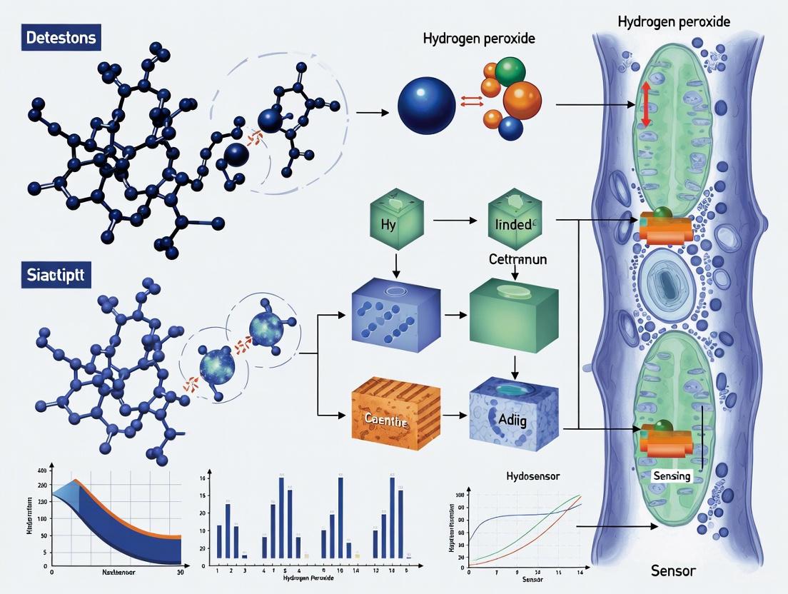
The real-time monitoring of hydrogen peroxide (H2O2) in living plants is crucial for understanding early stress signaling mechanisms, yet remains challenging due to the low concentrations of this signaling molecule and interference from plant autofluorescence. This technical guide details the design and synthesis of a novel optical nanosensor that integrates the unique properties of aggregation-induced emission (AIE) fluorophores with polymetallic oxomolybdates (POMs) to address these challenges. The developed nanosensor enables non-destructive, species-independent monitoring of stress-induced H2O2 signals in living plants with high sensitivity and specificity, providing a reliable optical tool for precision agriculture and plant biology research [8].
The integration of AIE fluorophores and POMs creates a synergistic "turn-on" sensing platform that overcomes the limitations of conventional fluorescent probes, including aggregation-caused quenching (ACQ), photobleaching, and interference from biological backgrounds. By leveraging the unique photophysical properties of AIE luminogens (AIEgens) and the H2O2-responsive characteristics of POMs, this nanosensor represents a significant advancement in plant chemical sensing technology [8] [33].
Fundamental Principles and Design Strategy
AIE Fluorophores: Overcoming ACQ Limitations
Traditional fluorophores often suffer from aggregation-caused quenching (ACQ), where fluorescence intensity decreases significantly at high concentrations or in aggregated states. In contrast, AIE luminogens (AIEgens) exhibit weak emission in molecularly dispersed states but intense fluorescence in aggregated states. This unique property makes them ideal for biological sensing and imaging applications where high local concentrations are common [34] [33].
AIE Mechanism: The AIE effect originates from the restriction of intramolecular motion (RIM) in aggregated states. In solution, active molecular rotations and vibrations of AIEgens non-radiatively dissipate excited-state energy, resulting in weak fluorescence. In aggregated states, these motions are restricted, closing the non-radiative pathways and enabling efficient radiative decay [35] [33].
Advantages for Plant Sensing: AIEgens offer significant advantages for plant applications, including strong resistance to photobleaching, large Stokes shifts that minimize excitation background, and reliable signal output at high concentrations. These properties are particularly valuable for long-term monitoring of plant stress responses [34].
Polymetallic Oxomolybdates: Versatile Inorganic Clusters
Polyoxometalates (POMs) are a class of metal-oxide clusters with diverse structural configurations and tunable properties. Polymetallic oxomolybdates, specifically those containing molybdenum, exhibit several characteristics that make them ideal for H2O2 sensing applications [36] [37].
Structural Diversity: POMs can be categorized into several structural families, with Keggin, Wells-Dawson, Anderson, and Lindqvist structures being most common. These structures can incorporate various heteroatoms and transition metals, allowing precise tuning of their chemical and electronic properties [37].
H2O2 Responsive Mechanism: Molybdenum-based POMs contain oxygen vacancies that introduce localized defect states, facilitating adsorption and activation of H2O2 molecules on their surface. The mixed-valence state of Mo^5+ and Mo^6+ enables charge-transfer transitions that are modulated by H2O2-induced oxidation, leading to changes in their near-infrared absorption properties [8].
Integrated Sensing Mechanism
The AIE-POM nanosensor operates through a fluorescence resonance energy transfer (FRET)-like mechanism where POMs act as efficient quenchers for AIE fluorophores in the initial state. The sensing process involves three fundamental steps:
Initial "Off-State": In the absence of H2O2, POMs are assembled on the surface of AIE nanoparticles, quenching their fluorescence through energy transfer due to the strong NIR absorption of POMs.
H2O2 Recognition: When H2O2 is present, it selectively oxidizes Mo^5+ to Mo^6+ in the POM structure, reducing the intervalence charge transfer between mixed-valence Mo centers.
Fluorescence "Turn-On": The decreased NIR absorption of oxidized POMs reduces their quenching efficiency, resulting in recovery of the AIE fluorophore's NIR-II fluorescence [8].
This mechanism is visualized in the following diagram:
Diagram 1: AIE-POM nanosensor sensing mechanism for H2O2 detection.
Synthesis and Fabrication Protocols
AIE Fluorophore Synthesis and Preparation
The core AIE fluorophore for NIR-II imaging employs a strong donor-acceptor-donor (D-A-D) molecular structure:
Molecular Design:
- Acceptor Unit: Benzo[1,2-c:4,5-c']bis[1,2,5]thiadiazole (BBTD) serves as a strong electron-withdrawing group with quinoidal structure, facilitating electron delocalization and reducing bandgap.
- Donor Units: Trimethylamine (TPA) acts as both electron-donor and molecular rotor, ensuring intramolecular rotation for AIE effect.
- π-Conjugated Bridge: Thiophene rings function as secondary donors and π-conjugated units, facilitating intramolecular charge transfer (ICT) from TPA to BBTD.
- Steric Hindrance Control: Branched carbon alkyl chains on thiophene provide tunable steric hindrance to prevent excessive aggregation [8].
Nanoparticle Formation: The NIR-II AIE dye is encapsulated into polystyrene (PS) nanospheres using the organic solvent swelling method to form AIE nanoparticles (AIENPs) with uniform size distribution and enhanced photostability [8].
POM Synthesis and Functionalization
Three types of POMs with varying NIR absorption properties were synthesized and evaluated as fluorescence quenchers:
Mo-POM Synthesis:
- Procedure: A one-pot synthesis from molybdate precursors under acidic conditions with controlled pH and temperature.
- Parameters: Reaction temperature (60-80°C), pH (2-4), and concentration of metal precursors determine final structure and properties [8].
Bimetallic POM Synthesis (Mo/Fe-POM and Mo/Cu-POM):
- Procedure: Incorporation of secondary metals (Fe or Cu) during synthesis creates oxygen vacancies and enhances H2O2 responsiveness.
- Characterization: X-ray photoelectron spectroscopy (XPS) analysis confirms mixed valence states of Mo^5+ and Mo^6+ with average oxidation states of 5.38, 5.49, and 5.40 for Mo-POM, Mo/Fe-POM, and Mo/Cu-POM, respectively [8].
Nanosensor Assembly
The complete nanosensor is assembled through co-assembly of AIENPs and POMs:
Assembly Protocol:
- Mass Ratio Optimization: AIE1035NPs and Mo/Cu-POM are co-assembled in mass ratios ranging from 0 to 100 to modulate NIR-II fluorescence performance.
- Characterization: Transmission electron microscopy (TEM) and elemental mapping confirm uniform assembly of Mo/Cu-POM on AIE1035NPs surface.
- Quality Control: Dynamic light scattering measures particle distribution index (PDI ≈ 0.078) and diameter (~230 nm).
- Surface Confirmation: Zeta potential measurements and XPS verify successful assembly [8].
The following workflow illustrates the complete experimental process:
Diagram 2: Experimental workflow for AIE-POM nanosensor development.
Performance Characterization and Optimization
Optical Properties and Sensing Performance
The AIE-POM nanosensor demonstrates exceptional optical properties tailored for plant imaging:
Table 1: Optical Performance Characteristics of AIE-POM Nanosensor
| Parameter | Value | Measurement Conditions |
|---|---|---|
| Detection Limit | 0.43 μM | In aqueous solution |
| Response Time | < 1 minute | Real-time measurement |
| Linear Range | Up to 1000 μM | Concentration gradient |
| Selectivity | Excellent for H2O2 | Against other ROS and biological analytes |
| pH Stability | Broad range (4-9) | Various pH conditions |
| Photostability | High resistance to photobleaching | Continuous laser irradiation |
Sensitivity and Selectivity:
- The Mo/Cu-POM based nanosensor shows superior response to H2O2 compared to other POM variants, with rapid decay effects observed at both NIR-I (750 nm) and NIR-II (1100 nm) wavelengths.
- Selectivity tests against common plant metabolites (sugars, amino acids, phytohormones) and other reactive oxygen species confirm high specificity for H2O2.
- The nanosensor maintains stability across physiological pH ranges and under prolonged laser irradiation, making it suitable for long-term plant imaging [8].
Comparison with Alternative H2O2 Probes
Table 2: Comparison of H2O2 Sensing Platforms
| Probe Type | Mechanism | LOD | Response Time | Plant Applications |
|---|---|---|---|---|
| AIE-POM Nanosensor | NIR-II fluorescence turn-on | 0.43 μM | < 1 min | Real-time in vivo monitoring across species |
| Electrochemical Sensor [38] | Current response at NiO/3DGH electrode | 5.3 μM | Seconds | Destructive analysis requiring tissue extraction |
| AIE-based Small Molecule [35] | Fluorescence enhancement at 500 nm | 49.74 nM | Minutes | Cellular imaging in plant tissues |
| Ratiometric AIE Probe [33] | Emission shift (435nm→550nm) | 6.0 μM | Minutes | Cellular imaging with self-calibration |
Data compiled from multiple sources [35] [38] [8]
Experimental Implementation in Plant Systems
Plant Preparation and Treatment
Plant Materials:
- The nanosensor has been validated across multiple species including Arabidopsis thaliana, lettuce, spinach, pepper, and tobacco.
- Plants are grown under controlled conditions (photoperiod, temperature, humidity) until specific developmental stages [8].
Stress Induction Protocols:
- Drought Stress: Withholding water for defined periods
- Salt Stress: Application of NaCl solutions (100-250 mM)
- Pathogen Challenge: Infection with bacterial or fungal pathogens
- Chemical Stimuli: Treatment with salicylic acid, methyl jasmonate, or cysteine to induce endogenous H2O2 production [34] [8].
Nanosensor Application and Imaging
Infiltration Methods:
- Leaf Infiltration: Using needleless syringe for gentle pressure-based infiltration
- Root Uptake: Immersion of root systems in nanosensor solution
- Stem Injection: Microinjection for stem tissues
Imaging Systems:
- NIR-II Microscopy: For cellular and subcellular resolution
- Macroscopic Whole-Plant Imaging: For systemic stress response monitoring
- Time-Lapse Imaging: For tracking H2O2 dynamics over hours to days [8].
Data Analysis and Machine Learning Integration
Image Processing Pipeline:
- Background Subtraction: Removing autofluorescence and scattering effects
- Signal Quantification: Converting fluorescence intensity to H2O2 concentration
- Spatiotemporal Mapping: Visualizing H2O2 distribution patterns
Machine Learning Classification:
- A dedicated machine learning model incorporates datasets collected by the nanosensor
- The model accurately classifies plant responses to different stress types with >96.67% accuracy
- This enables automated stress identification and severity assessment [8].
Research Reagent Solutions
Table 3: Essential Research Reagents for AIE-POM Nanosensor Development
| Reagent/Category | Function/Purpose | Examples/Specifications |
|---|---|---|
| AIE Fluorophores | NIR-II signal reporter | AIE1035 with D-A-D structure (BBTD acceptor, TPA donors) |
| POM Quenchers | H2O2 recognition and fluorescence modulation | Mo/Cu-POM with oxygen vacancies for enhanced H2O2 response |
| Encapsulation Matrix | Nanoparticle formation and stability | Polystyrene (PS) nanospheres via solvent swelling method |
| Characterization Tools | Structural and optical validation | TEM, XPS, DLS, fluorescence spectroscopy |
| Plant Materials | Biological validation systems | Arabidopsis, lettuce, spinach, pepper, tobacco |
| Stress Inducers | Eliciting H2O2 production | NaCl, pathogens, phytohormones, cysteine |
Data compiled from multiple sources [35] [34] [8]
The integration of AIE fluorophores with polymetallic oxomolybdates represents a significant advancement in optical nanosensor technology for plant science research. This platform combines the exceptional photostability and large Stokes shifts of AIEgens with the selective H2O2 responsiveness of POMs, enabling real-time, non-destructive monitoring of plant stress signaling in the biologically transparent NIR-II window.
Future developments in this field will likely focus on expanding the chemical diversity of both AIE components and POM structures to target additional signaling molecules, creating multiplexed sensing platforms, and further miniaturizing imaging systems for field applications. The integration of machine learning algorithms with sensor data analysis, as demonstrated in recent work, provides a powerful approach for automated stress diagnosis and prediction [8].
As these technologies mature, AIE-POM nanosensors are poised to become indispensable tools for fundamental plant biology research, crop improvement programs, and precision agriculture applications, ultimately contributing to enhanced food security and sustainable agricultural practices.
Real-Time Monitoring of Wound-Induced H₂O₂ Signaling Waves
Hydrogen peroxide (H₂O₂) is a crucial reactive oxygen species (ROS) that functions as a central signaling molecule in plant stress responses. The real-time monitoring of wound-induced H₂O₂ signaling waves represents a significant advancement in understanding plant systemic signaling networks. Traditional molecular biology methods have been limited in capturing the spatiotemporal dynamics of these rapid signaling events, as they often require destructive sampling and lack temporal resolution [39].
The emergence of optical nanosensor technology has revolutionized this field by enabling non-destructive, real-time, and species-independent detection of H₂O₂ in living plants [40] [8]. These nanobionic approaches allow researchers to decode the sophisticated internal communication systems that plants use to respond to stresses such as mechanical injury, pathogen infection, heat, and light damage [39]. This technical guide explores the fundamental principles, methodologies, and applications of these cutting-edge technologies within the broader context of optical nanosensors for hydrogen peroxide detection in living plant research.
H₂O₂ Signaling Waves in Plants: Core Mechanism
The Wound-Induced Signaling Pathway
Upon wounding, plants initiate a coordinated defense response that involves the rapid generation and propagation of H₂O₂ waves. This signaling cascade begins at the wound site and propagates systemically through plant tissues, preparing distant tissues for potential subsequent attacks [40].
The core mechanism involves the activation of NADPH oxidase (specifically the RbohD isoform) at the plasma membrane, which produces superoxide that is rapidly converted to H₂O₂ [40]. This H₂O₂ then activates calcium-permeable channels, particularly glutamate-receptor-like channels GLR3.3 and GLR3.6, leading to calcium influx that further activates adjacent NADPH oxidase complexes [40]. This self-propagating cycle enables the rapid spread of the H₂O₂ wave across long distances through plant vasculature and tissues.
Theoretical models suggest that purely diffusive transmission of intracellular H₂O₂ signals over distances of 10 μm requires high signal amplitudes and rapid enzymatic degradation to be feasible, indicating that relay stations or amplification mechanisms are likely necessary in biological systems [41]. The presence of relaying stations in the cytosol is a prerequisite for effective calcium-mediated signaling, though similar relaying stations for H₂O₂ have not yet been definitively identified in plant cells [41].
Figure 1: H₂O₂ Signaling Pathway. This diagram illustrates the self-propagating cycle of wound-induced H₂O₂ signaling in plants, involving key components such as NADPH oxidase RbohD and calcium-permeable channels GLR3.3 and GLR3.6.
Quantitative Propagation Characteristics
Research using optical nanosensors has revealed that the H₂O₂ concentration profile following wounding follows a characteristic logistic waveform across multiple plant species [40]. The propagation speed of these waves varies significantly between species, reflecting differences in their signaling architectures and defense strategies.
Table 1: H₂O₂ Wave Propagation Speeds Across Plant Species
| Plant Species | Common Name | Wave Speed (cm min⁻¹) |
|---|---|---|
| Lactuca sativa | Lettuce | 0.44 |
| Eruca sativa | Arugula | Not Specified |
| Spinacia oleracea | Spinach | Not Specified |
| Blitum capitatum | Strawberry Blite | Not Specified |
| Rumex acetosa | Sorrel | Not Specified |
| Arabidopsis thaliana | Thale Cress | 3.10 |
The variation in wave propagation speeds, ranging from 0.44 cm min⁻¹ in lettuce to 3.10 cm min⁻¹ in Arabidopsis thaliana [40], suggests species-specific adaptations in wound signaling efficiency. This quantitative data provides insights into the relationship between signaling speed and defense strategy across different plant types.
Optical Nanosensor Technology
Fundamental Sensing Mechanisms
Optical nanosensors for H₂O₂ detection employ various fluorescence-based mechanisms that enable real-time monitoring with high specificity and sensitivity. The evolution of these sensors has progressed from basic fluorescence detection to sophisticated nanoparticle-based ratiometric sensors with AI integration [24].
The primary sensing mechanisms include:
Fluorescence Quenching/Activation: This approach involves the reduction (turn-off) or enhancement (turn-on) of fluorescence intensity upon interaction with H₂O₂. Turn-on sensors are particularly valuable for biological applications as the bright signal produced against a dark background is easier to detect and less prone to interference [24].
Förster Resonance Energy Transfer (FRET): This mechanism operates through energy transfer between two closely positioned fluorescent chromophores—a donor and an acceptor—resulting in a measurable shift in fluorescence that can be correlated with H₂O₂ concentration [24].
Aggregation-Induced Emission (AIE): AIE fluorophores exhibit enhanced fluorescence efficiency in aggregated states, providing stable luminescent properties for continuous monitoring applications [8].
Recent advancements have incorporated near-infrared (NIR) and second near-infrared (NIR-II) imaging technologies to overcome limitations of traditional fluorescence detection, particularly interference from chlorophyll autofluorescence in plant tissues [8].
Nanosensor Architectures and Compositions
The architectural design of H₂O₂ nanosensors has evolved to incorporate various nanomaterials that enhance sensitivity, selectivity, and stability:
Carbon Nanotube-Based Sensors: Single-walled carbon nanotubes wrapped in specially designed polymers can detect H₂O₂ through changes in near-infrared fluorescence intensity [42]. These sensors benefit from the unique photophysical properties of carbon nanotubes, including photostability and resistance to photobleaching.
Polymetallic Oxomolybdates (POMs) Systems: These incorporate NIR-II fluorophores with AIE properties co-assembled with POMs as fluorescence quenchers [8]. The inherent oxygen vacancies in POMs confer H₂O₂-responsive properties, where interaction with H₂O₂ decreases NIR absorbance and recovers the NIR-II fluorescence signal.
Hybrid Nanosensors: Advanced designs such as AIE1035NPs@Mo/Cu-POM combine AIE nanoparticles with metal-doped POMs to create systems with strong fluorescence "turn-off" effects that activate specifically in the presence of H₂O₂ [8].
Table 2: Nanosensor Architectures for H₂O₂ Detection
| Nanosensor Type | Core Components | Detection Mechanism | Response Time | Sensitivity |
|---|---|---|---|---|
| Carbon Nanotube-Based | SWCNT + Functional Polymer | NIR Fluorescence Intensity Change | Not Specified | Not Specified |
| POM-Based NIR-II | AIE Fluorophore + Mo/Cu-POM | Quenching/Activation | 1 minute | 0.43 μM |
| Traditional Fluorescent | Organic Dyes + Recognition Elements | Fluorescence Quenching | Slower | Lower |
Experimental Protocols
Nanosensor Implementation Workflow
The implementation of optical nanosensors for monitoring wound-induced H₂O₂ signaling waves follows a systematic workflow that ensures reliable and reproducible results:
Figure 2: Experimental Workflow. This diagram outlines the key steps in implementing optical nanosensors for monitoring wound-induced H₂O₂ signaling waves in plants.
Sensor Preparation and Application
The Lipid Exchange Envelope Penetration (LEEP) method is commonly employed to incorporate nanosensors into plant tissues [39]. This protocol involves:
Sensor Solution Preparation: Prepare nanosensor solutions at appropriate concentrations in biocompatible buffers. For carbon nanotube-based sensors, this involves dispersing the nanotubes with specific polymers that enable H₂O₂ recognition.
Plant Material Preparation: Select healthy, uniformly grown plants. Arabidopsis thaliana, lettuce, arugula, spinach, strawberry blite, and sorrel have been successfully used in previous studies [40].
Sensor Application: For leaf tissues, use syringe infiltration or vacuum infiltration methods to introduce nanosensors into the apoplastic space. Alternatively, microneedles can be used for highly localized, tissue-specific sensing [42].
Wound Induction and Imaging
Controlled wounding protocols are essential for generating reproducible H₂O₂ signaling waves:
Standardized Wounding: Implement consistent mechanical wounding using precision tools such as laser ablation or standardized mechanical pressure. The wounding intensity should be controlled to ensure comparable results across experiments.
Real-time Imaging Setup: Utilize NIR-II microscopy systems or macroscopic whole-plant imaging systems to capture the spatiotemporal dynamics of H₂O₂ waves [8]. The imaging should begin immediately before wounding to establish baseline fluorescence.
Signal Acquisition: Collect time-series data with appropriate temporal resolution to capture the rapid propagation of H₂O₂ waves. The typical imaging duration depends on the plant species and wounding intensity but generally spans from minutes to hours.
Data Processing and Machine Learning Integration
Advanced data processing techniques are employed to extract meaningful information from the fluorescence imaging data:
Image Preprocessing: Apply background subtraction, flat-field correction, and noise reduction algorithms to raw fluorescence images.
Signal Quantification: Convert fluorescence intensity to H₂O₂ concentration using appropriate calibration curves established for each sensor type.
Wave Propagation Analysis: Calculate wave speed and amplitude by analyzing the spatiotemporal progression of the H₂O₂ signal across the plant tissue.
Machine Learning Classification: Implement machine learning models, such as the one demonstrated with >96.67% accuracy in classifying plant responses to different stress types [8], to automate the interpretation of complex signaling patterns.
The Scientist's Toolkit: Essential Research Reagents and Materials
Table 3: Research Reagent Solutions for H₂O₂ Signaling Studies
| Reagent/Material | Function | Example Specifications |
|---|---|---|
| Optical Nanosensors | H₂O₂ detection and quantification | SWCNT-based sensors; AIE1035NPs@Mo/Cu-POM for NIR-II imaging |
| Plant Growth Media | Standardized plant cultivation | Controlled nutrient composition for consistent plant development |
| Wounding Tools | Precise mechanical stress application | Laser ablation systems or standardized mechanical pressure devices |
| Fluorescence Imaging Systems | Real-time signal capture | NIR-II microscopy systems; Macroscopic whole-plant imagers |
| Image Analysis Software | Data processing and quantification | Custom algorithms for spatiotemporal analysis of wave propagation |
| Machine Learning Platforms | Pattern recognition and classification | TensorFlow or similar frameworks for stress response classification |
Advanced Applications and Future Directions
The integration of optical nanosensors with machine learning represents a transformative advancement in plant stress signaling research. The combination of these technologies enables not only the detection of H₂O₂ waves but also the classification of specific stress types with high accuracy [8]. This capability has significant implications for precision agriculture, where early identification of plant stress can inform targeted interventions to optimize crop health and productivity.
Future developments in this field are likely to focus on several key areas:
Multiplexed Sensing Platforms: Combining multiple sensors to simultaneously detect H₂O₂ and related metabolites, creating comprehensive hormone signaling profiles that offer deeper insights into plant stress responses [42].
Field-Deployable Systems: Translating laboratory technologies into practical, field-ready solutions for agricultural monitoring, potentially through collaboration with industrial urban farming partners [42].
Enhanced Spatial Resolution: Utilizing microneedles and other minimally invasive techniques for highly localized, tissue-specific sensing that provides unprecedented resolution of signaling events [42].
Closed-Loop Feedback Systems: Integrating sensing capabilities with actuation systems for automated plant stress management, similar to proposed smart bandage technologies for wound healing [43].
These advancements will continue to enhance our understanding of plant signaling networks while providing practical tools for addressing challenges in food security and sustainable agriculture.
Machine Learning-Enhanced Stress Classification with Over 96% Accuracy
The integration of advanced machine learning (ML) techniques with physiological data represents a transformative frontier in biosensing. This whitepaper details methodologies for achieving stress classification with over 96% accuracy, framing these technological advances within an innovative research context: the development of optical nanosensors for hydrogen peroxide (H₂O₂) detection in living plants. H₂O₂ is a key signaling molecule in plant stress responses, and its precise quantification can serve as a robust, non-destructive biomarker for plant health [44] [24]. The machine learning paradigms that enable high-accuracy stress classification from complex physiological signals in humans are directly applicable to interpreting the optical data generated by nanosensors in plant systems, paving the way for real-time, automated plant stress monitoring.
High-Accuracy Machine Learning Approaches for Stress Classification
Recent research has demonstrated that deep learning models, which automatically extract features from raw or minimally processed physiological data, can significantly outperform traditional machine learning methods that rely on hand-crafted features [45]. The following table summarizes performance metrics of various models reported in recent studies.
Table 1: Performance of Machine Learning Models in Stress Classification
| Model | Accuracy | Data Modality | Key Advantage |
|---|---|---|---|
| Deep Neural Network (DNN) | 99.70% (Binary) [46] | Physiological signals from chest-worn sensors [46] | Automated feature learning; high robustness [46] |
| 1D Convolutional Neural Network | 99.80% (Binary) [45] | Physiological signals from chest-worn sensors [45] | Superior automatic feature extraction from raw signals [45] |
| Deep Neural Network (DNN) | 90.57% (3-Class) [46] | Physiological signals (WESAD dataset) [46] | Effective for multi-class classification tasks [46] |
| Support Vector Machine (SVM) | 95.00% [47] | Psychological survey data [47] | High performance on questionnaire-based data [47] |
| Deep Belief Network (DBN) | 66.23% [48] | Physical activity & lifestyle data [48] | Effective for structured, non-sensor data [48] |
The exceptional accuracy of DNNs and CNNs stems from their ability to learn hierarchical representations directly from raw input data, eliminating the need for manual feature engineering—a process that can be time-consuming and may discard critical information [45]. These models are particularly suited for processing the complex, high-dimensional data generated by biosensors.
Experimental Protocols for High-Accuracy Stress Detection
Data Collection and Preprocessing for Physiological Signals
The following protocol is derived from studies that achieved >99% accuracy using deep learning [46] [45]:
- Sensor Deployment: Collect data using a multi-sensor setup. Chest-worn systems provide high-fidelity signals, including Electrocardiogram (ECG), Electrodermal Activity (EDA), and Electromyography (EMG), sampled at 700 Hz [45]. Wrist-worn devices (e.g., Samsung Galaxy Watch3) offer a less obtrusive alternative, measuring Heart Rate (HR) and Photoplethysmography (PPG) to derive Pulse Rate Variability (PRV) [49].
- Stress Induction and Labeling: Induce stress states using standardized protocols such as the Trier Social Stress Test (TSST), which involves public speaking and mental arithmetic tasks [45]. Baseline (non-stress) data is collected during resting periods. Data segments are explicitly labeled as "stress" or "non-stress" for supervised learning.
- Data Segmentation: Segment the continuous physiological signal data into fixed-duration windows (e.g., 3-minute windows with a 10-second shift) to create multiple data samples for training and testing [49].
- Normalization: Apply min-max normalization to each feature per participant to account for individual differences in baseline physiology and to scale the data for optimal model performance [49].
Deep Neural Network Model Training
- Input Layer Configuration: Format the preprocessed data from each window into a 1D vector for input into the network. The size depends on the number of sensor channels and features used.
- Model Architecture: Implement a deep network architecture. A 1D Convolutional Neural Network (1D-CNN) is highly effective for temporal signal data [45].
- Training with Optimizers: Train the model using the Adam optimizer, which has been shown to achieve superior performance (99.7% accuracy with 64 epochs) compared to alternatives like Stochastic Gradient Descent (SGD) [46].
- Performance Validation: Evaluate the model using rigorous cross-validation techniques, such as Leave-One-Subject-Out Cross-Validation (LOSO-CV), to ensure generalizability across individuals and avoid overfitting [49].
Diagram 1: Experimental workflow for ML-based stress detection.
The Scientist's Toolkit: Research Reagent Solutions
The following reagents and materials are essential for developing and implementing high-accuracy stress classification systems, whether for human studies or plant biosensing research.
Table 2: Essential Research Reagents and Materials
| Item | Function & Application |
|---|---|
| WESAD Dataset [46] [45] | A publicly available benchmark dataset containing multi-sensor physiological data (wrist and chest) from subjects under stress and non-stress conditions, used for training and validating ML models. |
| Prussian Blue (PB) [50] | An "artificial peroxidase" used in electrochemical H₂O₂ sensors. It catalyzes H₂O₂ reduction at low voltages, minimizing interference, and is a key material for translating sensing concepts [50]. |
| Quantum Dots (QDs) [44] [24] | Nanoscale semiconductors with exceptional optical properties (e.g., high quantum yield, photostability) used as fluorophores in optical nanosensors for H₂O₂ detection. |
| 3D Graphene Hydrogel [38] | A nanostructured carbon material with a high surface area, excellent conductivity, and porous structure. It serves as an ideal substrate for anchoring catalytic nanoparticles in enzymeless H₂O₂ sensors [38]. |
| NiO Octahedrons [38] | A transition metal oxide nanomaterial with high electrocatalytic activity for H₂O₂ oxidation/reduction. When decorated on 3D graphene, it creates a highly sensitive composite sensing electrode [38]. |
| Ionic Liquids (ILs) [50] | Salts in a liquid state with high conductivity and stability. Used as modification agents in electrode pastes to enhance electron transfer and improve the performance of electrochemical sensors [50]. |
Application to Optical Nanosensors for H₂O₂ in Plants
The principles of high-accuracy stress classification can be directly applied to plant science through the development of optical nanosensors for H₂O₂. In plants, H₂O₂ is a central reactive oxygen species (ROS) produced in response to abiotic stresses (e.g., drought, salinity) and pathogen attacks [51] [24]. Real-time monitoring of H₂O₂ flux can provide an early and precise indicator of plant stress.
Fluorescent nanosensors, such as those based on quantum dots or other nanomaterials, can be designed to change their emission properties (intensity, wavelength) upon interaction with H₂O₂ [44] [24]. The resulting optical signals form a complex, high-dimensional dataset analogous to human physiological data. A deep learning model can be trained to classify these optical signals, correlating specific signal patterns with distinct plant stress states (e.g., "early drought stress," "pathogen infection") with high accuracy.
This integrated system allows for continuous, non-destructive monitoring of plant health in agricultural settings. The workflow involves H₂O₂ detection by the nanosensor, optical signal acquisition, and automated stress classification by a pre-trained ML model, enabling rapid intervention and precision agriculture practices.
Diagram 2: Plant stress detection via H₂O₂ nanosensors and ML.
The integration of advanced optical sensors and automated phenotyping platforms is revolutionizing plant science, enabling precise, non-invasive monitoring of physiological responses across diverse species. This whitepaper explores the transition of monitoring technologies from model organisms like Arabidopsis thaliana to agriculturally significant crops, with a specific focus on hydrogen peroxide (H2O2) detection using near-infrared fluorescent nanosensors. These technologies provide real-time data on plant stress signaling, growth dynamics, and productivity, forming a critical knowledge base for improving crop resilience and yield in challenging environmental conditions.
Plant phenomics has emerged as a crucial interdisciplinary field integrating biology, engineering, and bioinformatics to quantitatively assess plant growth, development, and responses to environmental stimuli [52]. The fundamental equation P = G × E (phenotype = genotype × environment) underscores the complexity of plant traits, which are influenced by both genetic constitution and environmental conditions encountered during growth [52]. Traditional plant phenotyping methods have been limited by low throughput and subjective measurements, but recent technological advances have enabled automated, high-precision monitoring that can be applied across species boundaries.
Arabidopsis thaliana has served as the primary model organism for developing these technologies due to its well-characterized genome, small size, and short life cycle [52] [53]. The research community has established comprehensive phenotyping workflows for Arabidopsis that quantify architectural and physiological parameters related to agronomically relevant traits [52]. These foundational approaches are now being successfully adapted to crop species, creating opportunities for species-independent monitoring systems that can detect early stress responses and optimize agricultural management practices.
Core Principles of Optical Nanosensors for H2O2 Monitoring
Nanosensor Design and Operating Mechanism
Near-infrared (nIR) fluorescent single-walled carbon nanotubes (SWCNTs) have been engineered as highly sensitive biosensors for detecting hydrogen peroxide (H2O2), a key signaling molecule associated with the onset of plant stress [54]. These optical nanosensors function through a fluorescence quenching mechanism in the presence of H2O2, with selectivity against other stress-associated signaling molecules within the plant physiological range (10-100 μM H2O2) [54]. The nIR fluorescence response occurs at wavelengths beyond 900 nm, enabling deep tissue penetration and minimizing interference from plant autofluorescence.
The exceptional biocompatibility of these SWCNT-based sensors has been demonstrated through minimal impact on plant physiology, with similar leaf cell death (<5%) and photosynthetic rates observed compared to control plants without nanosensors [54]. This preservation of normal plant function is critical for accurate monitoring of stress responses without introducing artifacts from the measurement technology itself.
Advantages for Species-Independent Monitoring
The nIR fluorescence approach offers several significant advantages for cross-species applications:
- Non-invasiveness: Sensors interface with plant leaves without requiring tissue extraction or disruption of physiological processes [54]
- Real-time monitoring: Enables continuous tracking of H2O2 dynamics during stress progression
- High specificity: Selective against other reactive oxygen species and signaling molecules
- Remote capability: Allows imaging of plant health responses without physical contact [54]
- Scalability: Compatible with high-throughput phenotyping platforms for large-scale studies
Quantitative Performance Data Across Species
Table 1: Performance Metrics of H2O2 Nanosensors in Plant Systems
| Parameter | Arabidopsis thaliana | Crop Applications | Measurement Technique |
|---|---|---|---|
| Detection Range | 10-100 μM H2O2 [54] | Comparable physiological range expected | Fluorescence quenching |
| Detection Specificity | Selective against other ROS and stress signals [54] | Similar selectivity profile assumed | Spectral analysis |
| Stress Response Detection | UV-B light (-11%), high light (-6%), flg22 peptide (-10%) [54] | Species-specific variations expected | nIR fluorescence imaging |
| Biocompatibility | Similar leaf cell death (<5%) and photosynthetic rates to controls [54] | Requires species-specific validation | Chlorophyll fluorescence, viability staining |
| Spatial Resolution | Leaf-level monitoring demonstrated [54] | Scalable to larger crop leaves | Remote nIR imaging |
Table 2: High-Throughput Phenotyping Platforms for Species-Independent Monitoring
| Platform Component | Arabidopsis Implementation | Crop Adaptation | Extracted Features |
|---|---|---|---|
| Imaging Systems | VIS, FLUO, NIR cameras [52] | Similar multi-sensor approach | 310+ features (geometric, color-related) [52] |
| Automated Handling | phenoSeeder for individual seed processing [53] | Scalable robotic systems | Mass, volume, dimensions, color [53] |
| Growth Monitoring | Growscreen for early development [53] | Larger-scale conveyor systems | 2D leaf area, germination time, growth rates [53] |
| Data Integration | Seed-to-plant tracking pipeline [53] | Cross-referencing with environmental data | Trait correlations across generations [53] |
Detailed Experimental Protocols
Nanosensor Application and H2O2 Imaging
Materials Required:
- Near-infrared fluorescent SWCNT sensors [54]
- Arabidopsis or crop plants at desired developmental stage
- nIR imaging system with >900 nm detection capability
- Controlled environment for stress applications
Procedure:
- Sensor Preparation: Prepare SWCNT suspension in appropriate buffer solution
- Plant Interface: Apply nanosensors to leaf surfaces without inducing physical damage
- Baseline Imaging: Acquire pre-stress nIR fluorescence images as reference
- Stress Application: Implement specific stress conditions (UV-B, high light, pathogen elicitors)
- Time-Series Monitoring: Capture nIR fluorescence images at regular intervals
- Data Quantification: Calculate fluorescence quenching relative to baseline
- Validation: Correlate with traditional stress markers where possible
This protocol has been successfully implemented for detecting H2O2 responses to UV-B light (-11% fluorescence), high light (-6%), and pathogen-related peptide flg22 (-10%), but not mechanical wounding (<3% change) [54].
High-Throughput Phenotyping Workflow
Materials Required:
- Automated phenotyping system (e.g., LemnaTec Scanalyzer) [52]
- RGB, fluorescence, and NIR cameras [52]
- Image analysis software (e.g., Integrated Analysis Platform - IAP) [52]
- Controlled growth environment
Procedure:
- System Configuration: Set up multi-sensor imaging system with appropriate zoom levels for plant developmental stage [52]
- Image Acquisition: Capture daily top-view images using VIS, NIR, and FLUO imaging procedures [52]
- Reference Imaging: Collect blank reference images before each imaging run [52]
- Data Storage: Save images as uncompressed PNG files for subsequent analysis [52]
- Feature Extraction: Use IAP software to compute 310+ features including geometric and color-related traits [52]
- Statistical Analysis: Perform outlier correction and correlation analysis with manual measurements [52]
This automated approach enables non-invasive monitoring of plant growth and development, with the capacity to process thousands of plants simultaneously [52].
Signaling Pathways and Experimental Workflows
Diagram 1: H₂O₂ Nanosensor Stress Detection Pathway
Diagram 2: Automated Seed-to-Plant Tracking Pipeline
Research Reagent Solutions and Essential Materials
Table 3: Key Research Reagents and Materials for Plant Monitoring Studies
| Reagent/Material | Function/Application | Specifications |
|---|---|---|
| SWCNT Nanosensors | H2O2 detection in plant tissues [54] | nIR fluorescence (>900 nm), selective for H2O2 in 10-100 μM range [54] |
| phenoSeeder System | Automated seed handling and phenotyping [53] | Measures mass, volume, dimensions; improved for very small seeds [53] |
| LemnaTec Scanalyzer | High-throughput plant imaging [52] | VIS, NIR, FLUO cameras; controlled environment [52] |
| IAP Software | Image analysis and feature extraction [52] | Computes 310+ features from multi-spectral images [52] |
| Arabidopsis Seeds | Model system for initial validation [52] [53] | Genotype C248 (NASC ID N22680) [52] |
The transition of monitoring technologies from Arabidopsis models to crop species represents a paradigm shift in plant science and agricultural research. Optical nanosensors for H2O2 detection, combined with automated phenotyping platforms, provide powerful tools for understanding plant stress responses in real-time without destructive sampling. These species-independent approaches enable researchers to correlate early molecular signaling events with whole-plant physiological responses, creating opportunities for predictive agriculture and improved crop management strategies.
Future developments in this field will likely focus on multiplexed sensing capabilities for simultaneous detection of multiple signaling molecules, enhanced spatial resolution for subcellular monitoring, and integration with genomic data for comprehensive phenotype-to-genotype analyses. As these technologies become more accessible and scalable, they have the potential to transform both basic plant research and applied agricultural practices, contributing to global food security challenges.
Overcoming Technical Hurdles in Nanosensor Performance and Implementation
The detection of hydrogen peroxide (H₂O₂) in living plants using optical nanosensors represents a significant advancement in plant physiology research. However, the complex chemical environment within plant cells, characterized by the presence of multiple reactive oxygen species (ROS) with similar chemical reactivities, poses a substantial challenge for selective H₂O₂ detection [55]. ROS, including superoxide anion (O₂•⁻), hydroxyl radical (•OH), singlet oxygen (¹O₂), hypochlorite (ClO⁻), and peroxynitrite (ONOO⁻), coexist with H₂O₂ in various plant compartments and often at comparable concentrations [56]. The short lifetime and low abundance of many ROS further complicate their discrimination [55]. This technical guide provides a comprehensive framework for ensuring selectivity in H₂O₂ detection, outlining strategic sensor design principles, material selection criteria, and experimental validation protocols specifically tailored for plant research applications.
Fundamental ROS Chemistry and Cross-Reactivity Mechanisms
The Plant ROS Network
In plant systems, ROS form an interconnected network where species interconvert through specific biochemical pathways. Superoxide anion (O₂•⁻), primarily generated in electron transport chains, is dismutated to H₂O₂ by superoxide dismutase (SOD) [56]. H₂O₂ can then be converted to highly reactive hydroxyl radicals (•OH) via Fenton reactions in the presence of transition metal ions like Fe²⁺ or Cu²⁺ [56]. This inherent interconnectivity means that manipulating one ROS often affects others, creating significant challenges for selective detection.
Common Interference Pathways in Optical Detection
Interference occurs when nonspecific reactions between the nanosensor and non-target ROS produce optical signals indistinguishable from the H₂O₂ response. The most prevalent interference mechanisms include:
- Oxidation of recognition elements by stronger oxidants (e.g., •OH, ONOO⁻) designed for H₂O₂ detection
- Energy transfer quenching via collision with multiple ROS species
- Direct electron transfer from photoexcited states to various oxidizing agents
- Nanomaterial surface oxidation altering optical properties regardless of the specific ROS involved
The highly reactive hydroxyl radical (•OH) represents a particularly challenging interferent due to its nonspecific oxidation of most organic recognition elements [56].
Strategic Design Principles for Selective H₂O₂ Nanosensors
Molecular Recognition Element Engineering
The foundation of selective H₂O₂ detection lies in engineering recognition elements with specific kinetic and thermodynamic preferences for H₂O₂ over other ROS.
Table 1: Recognition Elements for Selective H₂O₂ Detection
| Recognition Element | Mechanism | Selectivity Advantages | Limitations in Plant Systems |
|---|---|---|---|
| Boronic acid derivatives | Oxidation to phenol | Fast response to H₂O₂; relatively inert to O₂•⁻ | Sensitive to •OH and ONOO⁻ |
| Aryl sulfonate esters | H₂O₂-mediated deprotection | Good discrimination against ClO⁻ | Potential interference from cellular esterases |
| Transition metal oxides | Catalytic decomposition | Tunable selectivity via metal selection | May catalyze Fenton reactions |
| Peroxidase mimics | Enzyme-like catalysis | High specificity through biomimicry | pH-dependent activity |
Boronic acid-based probes are particularly valuable for plant applications due to their fast reaction kinetics with H₂O₂ and relatively slow response to other ROS under physiological conditions [44]. The recognition mechanism involves specific oxidation of boronic acid to phenol, providing a distinct optical signal change that can be discriminated from interference patterns.
Nanomaterial Platform Selection
The nanomaterial scaffold significantly influences selectivity through spatial confinement, energy transfer modulation, and surface chemistry effects.
Table 2: Nanomaterial Platforms for Selective H₂O₂ Sensing
| Nanomaterial Platform | Selectivity Mechanisms | Optical Readout | Compatibility with Plant Systems |
|---|---|---|---|
| Quantum Dots (QDs) | Electron transfer blocking | Fluorescence intensity | Moderate; potential heavy metal toxicity |
| Mesoporous Silica NPs | Molecular sieving | Ratiometric fluorescence | High; excellent biocompatibility |
| Metal-Organic Frameworks | Size-selective pores | Luminescence lifetime | Emerging; unestablished long-term effects |
| Polymer Nanoparticles | Polarity-based partitioning | Colorimetric change | High; tunable surface chemistry |
Quantum dots (QDs) provide exceptional optical properties and high fluorescence quantum yields for sensitive detection. Their surface chemistry can be engineered to preferentially interact with H₂O₂ through careful ligand selection and surface passivation [44]. Mesoporous silica nanoparticles (MSNs) offer tunable pore structures (2-50 nm) that can exclude larger ROS molecules while allowing H₂O₂ diffusion, providing size-based selectivity [44].
Advanced Signaling Mechanisms
Ratiometric sensing approaches significantly enhance selectivity by providing internal calibration that compensates for environmental variables and nonspecific interactions. Hybrid nanosystems incorporating both H₂O₂-responsive and reference fluorophores enable quantitative detection through intensity ratio measurements rather than absolute signal changes [44]. Fluorescence lifetime imaging (FLIM) offers an additional dimension for discrimination, as H₂O₂-specific interactions typically produce distinct lifetime changes compared to other ROS [55].
Experimental Protocols for Selectivity Validation
Specificity Profiling Against Common ROS Interferents
Objective: To quantitatively determine the sensor's response to H₂O₂ relative to other biologically relevant ROS.
Reagents:
- Nanosensor suspension in appropriate buffer (e.g., 10 mM PBS, pH 7.4)
- H₂O₂ stock solution (100 mM in deionized water)
- Interferent stock solutions: KO₂ (O₂•⁻ source), NaOCl (ClO⁻ source), SIN-1 (ONOO⁻ source), Rose Bengal (¹O₂ source)
- Specific ROS scavengers: catalase (H₂O₂), SOD (O₂•⁻), L-histidine (¹O₂), D-mannitol (•OH)
Procedure:
- Prepare separate samples containing identical nanosensor concentration (0.1-1 mg/mL)
- Treat each sample with one of the following: H₂O₂ (10 μM), O₂•⁻ (10 μM), ClO⁻ (10 μM), ONOO⁻ (10 μM), ¹O₂ (10 μM)
- Record optical responses (fluorescence intensity/spectral shift) at predetermined time intervals
- Repeat measurements in the presence of specific scavengers to confirm signal origins
- Calculate response ratios (SignalInterferent/SignalH₂O₂) for each ROS
Data Interpretation: A selective H₂O₂ nanosensor should demonstrate at least 5-fold higher response to H₂O₂ compared to any other ROS at equimolar concentrations.
Competitive Interference Assay in Plant Extracts
Objective: To evaluate sensor performance in complex plant matrices containing multiple competing ROS.
Reagents:
- Plant tissue homogenate (e.g., from Arabidopsis leaves)
- Extraction buffer (50 mM phosphate buffer, pH 7.0, containing 0.1 mM EDTA)
- H₂O₂ standard solutions (0, 5, 10, 20, 50 μM)
- Nanosensor suspension
Procedure:
- Prepare plant extract by homogenizing tissue in cold extraction buffer (1:5 w/v)
- Centrifuge at 12,000 × g for 15 minutes at 4°C
- Spike supernatant with known H₂O₂ concentrations (0-50 μM)
- Add nanosensor and measure optical signals
- Construct calibration curve and compare with buffer-based standards
- Perform recovery calculations: (Measured H₂O₂/Spiked H₂O₂) × 100
Validation Criteria: Acceptable sensor performance demonstrates 85-115% recovery across the tested concentration range, indicating minimal matrix interference.
The Scientist's Toolkit: Essential Research Reagents
Table 3: Research Reagent Solutions for Selective H₂O₂ Detection
| Reagent/Category | Function in Selectivity Assurance | Example Products/Specifications |
|---|---|---|
| ROS Generators | Positive controls for interference testing | KO₂ (O₂•⁻), SIN-1 (ONOO⁻), H₂O₂/UV (•OH), Rose Bengal/light (¹O₂) |
| ROS Scavengers | Specificity confirmation in control experiments | Catalase (H₂O₂), Superoxide Dismutase (O₂•⁻), Sodium azide (¹O₂), D-mannitol (•OH) |
| Selective Fluorophores | Ratiometric sensing elements | Boronate-functionalized dyes (H₂O₂), Hydro-Cy3 (ONOO⁻), APF (•OH/ONOO⁻) |
| Nanoscaffolds | Platform for sensor assembly | Mesoporous silica NPs (100-200 nm), Carboxylated QDs, Graphene oxide sheets |
| Plant Compatibility Agents | Reduce nonspecific interactions | Polyethylene glycol (PEGylation reagents), Cell-penetrating peptides (tat, penetratin) |
Visualization of Selectivity Strategies and Experimental Workflows
Selectivity Strategy Framework
Experimental Validation Workflow
Achieving selective H₂O₂ detection in living plants requires a multifaceted approach combining selective recognition chemistry, appropriate nanomaterial engineering, and rigorous validation protocols. The strategies outlined in this guide provide a pathway for developing robust optical nanosensors capable of discriminating H₂O₂ from interfering ROS species in complex plant environments. As these technologies mature, they will enable unprecedented insights into ROS signaling networks and oxidative stress responses in plant physiology, with significant implications for agricultural biotechnology, crop improvement, and plant stress resilience research. Future directions will likely focus on multimodal detection platforms, subcellular targeting strategies, and field-deployable systems for real-time plant health monitoring.
Optimizing Biocompatibility and Minimizing Phytotoxicity
The integration of optical nanosensors for hydrogen peroxide (H₂O₂) detection in living plants represents a transformative approach for decoding plant stress signalling in real-time. However, the successful implementation of this technology depends critically on optimizing biocompatibility and minimizing phytotoxicity. Plants possess sophisticated internal communication systems, utilizing H₂O₂ as a key signalling molecule that propagates in waveforms following stress events such as wounding, infection, or light damage [40] [57]. These signals, which can be tracked using non-destructive optical nanosensors, trigger defense mechanisms and secondary metabolite production [57]. The phytotoxicity challenge emerges from the potential for nanomaterials to disrupt these delicate signalling pathways, cause oxidative stress, or induce morphological and anatomical damage that compromises plant health [58] [59]. This technical guide provides a comprehensive framework for researchers developing plant nanosensor technologies, with emphasis on rigorous safety assessment, material selection, and experimental protocols that balance detection capability with physiological preservation.
Core Principles: Phytotoxicity and Biocompatibility
Phytotoxicity Mechanisms and Manifestations
Phytotoxicity refers to the detrimental effects exerted by substances on plant physiology, morphology, and development. In the context of nanosensor deployment, these effects can operate through multiple mechanisms:
- Cellular and Subcellular Damage: Nanoparticles can induce oxidative stress through reactive oxygen species (ROS) generation, leading to lipid peroxidation, protein denaturation, and nucleic acid damage [58] [60]. This is particularly problematic for H₂O₂ detection as nanosensor-induced ROS can interfere with the natural signalling pathways being monitored.
- Growth and Developmental Impacts: Phytotoxic compounds can inhibit seed germination, reduce root and shoot elongation, decrease biomass accumulation, and cause anatomical abnormalities [58] [59]. Studies with nanofertilizers demonstrated 45-78% reductions in root length and 30-65% decreases in dry biomass compared with controls [58].
- Morphological and Anatomical Alterations: Visible symptoms including chlorosis, necrosis, wilting, tissue atrophy, and organ deformation serve as indicators of phytotoxicity [59]. These structural changes often precede biochemical and molecular disruptions.
Biocompatibility Optimization Strategies
Biocompatibility encompasses material properties that enable nanosensor function without disrupting plant physiological processes. Key optimization strategies include:
- Surface Functionalization: Modifying nanosensor surfaces with biocompatible coatings such as tetramethylammonium hydroxide (TMA) can significantly reduce phytotoxic responses while maintaining detection capabilities [60].
- Concentration Optimization: Implementing rigorous dose-response studies to identify concentration thresholds that balance sensor functionality with minimal biological impact, recognizing that low concentrations may potentially stimulate growth while higher concentrations induce stress [60].
- Material Selection: Choosing base materials with established biocompatibility profiles, such as certain iron oxide formulations that have demonstrated positive physiological effects at appropriate concentrations [60].
Table 1: Quantitative Phytotoxicity Parameters for Selected Nanomaterials
| Material | Test Species | Key Toxicity Parameters | EC50/Effective Concentration | Observed Effects |
|---|---|---|---|---|
| Nanofertilizer (NF1) | Lactuca sativa | Germination Index, Root Length | EC50 = 1.2% | 45-78% root reduction, 30-65% biomass decrease [58] |
| TMA-IONPs | Zea mays | Germination Rate, Mitotic Index | 38.0 mg/L (optimal) | Enhanced germination, increased chlorophyll, higher mitotic index [60] |
| Potassium Dichromate | Lactuca sativa | Seedling Size, Fresh Weight | 133.24 mg/L (EC50) | >20% size decrease, >50% fresh weight reduction [59] |
| Titanium Dioxide NPs | Multiple Species | Oxidative Stress Markers | Concentration-dependent | Varied by species; can mitigate salinity stress [61] |
Experimental Protocols for Assessment
Standardized Phytotoxicity Bioassays
Comprehensive phytotoxicity assessment requires integrated testing protocols that evaluate multiple physiological endpoints:
Seed Germination Assays:
- Follow OECD 208 guidelines with adaptations for nanosensor materials [58] [59].
- Surface-sterilize seeds (e.g., Lactuca sativa) using 5% sodium hypochlorite for 5 minutes, followed by three rinses with sterile deionized water [59].
- Place 10 seeds per sterile square Petri dish containing solid Hoagland's solution with 1.5% agar and test concentrations of nanosensor materials.
- Maintain under controlled conditions (20±2°C, 16h light:8h dark photoperiod, ~6000 lux light intensity) [59].
- Evaluate germination percentage daily until 50% emergence occurs in control groups (typically 4-14 days depending on species).
Endpoint Measurements:
- Calculate germination percentage: GP(%) = (Gs/n) × 100, where Gs = germinated seeds, n = total seeds [60].
- Measure root and hypocotyl length with precision calipers (mm precision).
- Determine fresh and dry biomass (after 24-48h at 60-70°C).
- Calculate germination index (GI) as percentage relative to control [58].
Advanced Phytotoxicity Assessment Using ViPTox
The Visual PhytoToxicity assessment (ViPTox) provides enhanced sensitivity for detecting subtle morphological damage:
- Implement a dichotomous key scoring system from 0 (normal seedling) to 10 (no germination) to categorize morphological alterations [59].
- Score specific abnormalities: absence of roots/leaves (score 9), chlorosis/necrosis (score 8), atrophy (scores 5-7), deformations (scores 3-4), size reduction (scores 1-2) [59].
- Calculate Phyto-Morphological Damage index: PMD = ∑(individual scores)/n, where n = total seedlings [59].
- Utilize blinded assessment by multiple independent observers to minimize subjectivity.
Table 2: Comparative Phytotoxicity Assessment Methods
| Method | Endpoint Measured | Sensitivity | Advantages | Limitations |
|---|---|---|---|---|
| Standard Germination Assay (OECD 208) | Germination percentage, root length | Moderate | Standardized, reproducible, simple | May miss subtle morphological effects [58] [59] |
| ViPTox Scoring System | Morphological and anatomical alterations | High | Detects sublethal effects, cost-effective, non-invasive | Requires training, somewhat subjective [59] |
| Biochemical Markers | Antioxidant enzymes, chlorophyll content | High | Reveals oxidative stress mechanisms | Destructive sampling, requires specialized equipment [60] |
| H₂O₂ Signalling Monitoring | Wave propagation speed, amplitude | Context-dependent | Directly relevant to nanosensor function | Requires specialized nanosensors [40] [57] |
H₂O₂ Signalling Wave Characterization
For nanosensor development specifically, characterizing baseline H₂O₂ signalling is essential:
- Utilize embedded carbon nanotube sensors to detect H₂O₂ concentration profiles post-wounding [40] [57].
- Measure waveform propagation speeds (ranging from 0.44 to 3.10 cm/min across species) and temporal patterns [40].
- Compare waveforms across species (lettuce, arugula, spinach, strawberry blite, sorrel, Arabidopsis thaliana) to establish normal signalling baselines [40].
- Validate nanosensor readings against electrochemical surface potential measurements [40].
Pathway Visualization
H₂O₂ Signalling and Detection Pathway
Phytotoxicity Assessment Workflow
Research Reagent Solutions
Table 3: Essential Research Materials for Phytotoxicity Assessment
| Reagent/Material | Function in Research | Application Notes |
|---|---|---|
| Lactuca sativa (Lettuce) Seeds | Model organism for phytotoxicity bioassays | Standardized sensitivity; recommended by OECD guidelines [58] [59] |
| Hoagland's Solution with Agar | Standardized growth medium for controlled conditions | Provides essential nutrients; solid matrix for uniform exposure [59] |
| Potassium Dichromate | Reference toxicant for assay validation | EC50 = 133.24 mg/L for Lactuca sativa; provides quality control [59] |
| Tetramethylammonium Hydroxide | Nanoparticle stabilizing agent | Enhates colloidal stability; reduces agglomeration [60] |
| Carbon Nanotube Optical Nanosensors | H₂O₂ detection in real-time | Species-independent detection; non-destructive monitoring [40] [57] |
| Raspberry Pi with Infrared Camera | Signal capture from nanosensors | Cost-effective imaging solution for H₂O₂ fluorescence [57] |
Optimizing biocompatibility and minimizing phytotoxicity represents a critical pathway for advancing optical nanosensor applications in living plants. The framework presented in this guide—integrating standardized phytotoxicity assessment, advanced morphological evaluation, and H₂O₂ signalling validation—provides researchers with a comprehensive methodology for developing effective, minimally intrusive plant nanosensing technologies. As these technologies evolve, their successful implementation will depend on maintaining this careful balance between detection capability and physiological preservation, ultimately enabling deeper understanding of plant communication systems while ensuring plant health and integrity.
Improving Sensor Stability and Longevity in Complex Plant Environments
The deployment of optical nanosensors for monitoring hydrogen peroxide (H₂O₂) in living plants represents a significant advancement in understanding plant stress signaling. However, the complex plant environment—characterized by variable pH, enzymatic activity, reactive oxygen species, and dynamic physiological conditions—poses substantial challenges to sensor stability and longevity [8] [62]. Maintaining consistent sensor performance under these conditions is paramount for obtaining reliable data in prolonged studies. This technical guide examines the fundamental mechanisms of sensor degradation and outlines strategic approaches for enhancing sensor robustness, focusing on material selection, engineering methodologies, and experimental validation techniques specifically framed within H₂O₂ sensing applications in plant systems.
Material Design for Enhanced Stability
Nanomaterial Selection and Functionalization
The core materials constituting the nanosensor directly determine its resilience against environmental stressors. Selecting appropriate components and applying protective functionalizations can significantly mitigate degradation pathways:
- Fluorophore Engineering: Aggregation-Induced Emission (AIE) fluorophores, such as AIE1035 with a donor-acceptor-donor (D-A-D) structure, demonstrate enhanced photostability compared to conventional fluorophores. Their molecular design, incorporating specific spatial hindrance and planar thiophene rings with branched carbon alkyl chains, prevents excessive aggregation and maintains fluorescence integrity under prolonged laser irradiation [8].
- Protective Matrices: Encapsulating sensitive components within polystyrene (PS) nanospheres via organic solvent swelling methods provides a physical barrier against enzymatic degradation and molecular leaching. This nano-confinement approach preserves sensor function while allowing analyte permeability [8].
- Stable Quencher Systems: Polymetallic oxomolybdates (POMs), particularly mixed-valence variants like Mo/Cu-POM, exhibit excellent H₂O₂ selectivity and maintain functionality across a range of pH conditions (pH 4-10). Their oxygen vacancies facilitate specific H₂O₂ interactions while resisting interference from other endogenous plant molecules [8].
Surface Chemistry and Biocompatibility
Strategic surface modifications minimize non-specific interactions and immune recognition in plant tissues:
- Charge Optimization: Zeta potential modulation through controlled assembly of charged components (e.g., negative AIE1035NPs with positive Mo/Cu-POM) improves colloidal stability and reduces agglomeration in ionic plant milieus [8].
- Biomimetic Coatings: Applying plant-derived molecular motifs or biocompatible polymers (e.g., poly(amic acid)) to nanoparticle surfaces can mitigate recognition by plant defense systems and subsequent encapsulation or degradation [62].
Table 1: Nanomaterial Properties and Their Impact on Sensor Stability
| Material Component | Key Property | Stability Enhancement | Tested Conditions |
|---|---|---|---|
| AIE1035 Fluorophore | Aggregation-Induced Emission | Enhanced photostability; resistant to photobleaching | Laser irradiation; various pH levels [8] |
| Mo/Cu-POM Quencher | Mixed valence state (Mo⁵⁺/Mo⁶⁺) | Selective H₂O₂ response; minimal interference | pH 4-10; various endogenous molecules [8] |
| Polystyrene Matrix | Physical encapsulation barrier | Prevents component leaching; maintains structural integrity | In plant tissues (Arabidopsis, lettuce, tobacco) [8] |
| Silver Nanoparticles | Colorimetric properties | Detection stability for nitroaromatic compounds | Linear range 10-600 mM [62] |
Engineering Robust Sensor Architectures
"Turn-On" Sensing Mechanisms
Activatable "turn-on" sensor designs, such as the AIE1035NPs@Mo/Cu-POM system, significantly improve signal-to-noise ratio and reduce false readings by remaining fluorescently silent until specifically activated by the target analyte. This approach minimizes background interference and light-induced damage during prolonged monitoring periods [8]. The mechanism relies on H₂O₂-responsive oxidation of Mo⁵⁺ to Mo⁶⁺ in POMs, which diminishes their quenching effect and activates NIR-II fluorescence from the AIE fluorophore.
NIR-II Optical Platforms
Utilizing the second near-infrared window (1000-1700 nm) for detection substantially improves sensor performance by reducing background autofluorescence from plant pigments like chlorophyll and increasing penetration depth through plant tissues. This spectral advantage allows for clearer signal acquisition and extends viable monitoring periods by minimizing phototoxic effects [8].
Experimental Protocols for Stability Assessment
In Vitro Stability Characterization
Prior to plant integration, comprehensive in vitro testing establishes baseline performance metrics under controlled conditions that simulate plant environments:
pH Stability Protocol:
- Prepare sensor suspensions in buffer solutions across pH range 3.0-9.0
- Incubate at 25°C with constant agitation (200 rpm)
- Measure fluorescence intensity (λex=980 nm, λem=1035 nm) at 0, 1, 2, 4, 8, 12, and 24-hour intervals
- Calculate signal retention percentage relative to initial measurement [8]
Photostability Assessment:
- Apply continuous laser irradiation at operational wavelength (980 nm)
- Measure fluorescence intensity decay over 60-minute period
- Calculate half-life of fluorescence signal and percentage recovery after 24-hour dark period [8]
Selectivity Testing:
- Expose sensor to potential interfering species (Ca²⁺, K⁺, Na⁺, glutathione, phytohormones)
- Measure fluorescence response compared to H₂O₂-induced signal
- Calculate selectivity coefficient for each potential interferent [8]
In Planta Longevity Evaluation
Validating sensor performance in living plant systems requires carefully controlled infiltration and monitoring procedures:
Sensor Infiltration Protocol:
- Prepare nanosensor suspension (230 nm diameter) in mild buffer (10 mM PBS, pH 6.0)
- Infiltrate into plant leaves (Arabidopsis, lettuce, tobacco) using needle-free syringe
- Allow 2-hour stabilization period before initiating experiments [8]
Longitudinal Monitoring Method:
- Establish baseline fluorescence using NIR-II microscopy system
- Apply controlled stresses (drought, salinity, pathogen exposure)
- Capture time-series fluorescence images at 1-minute intervals for initial response, then hourly for longevity assessment
- Quantify signal stability and sensor localization over 7-day period [8]
Table 2: Research Reagent Solutions for H₂O₂ Nanosensor Development
| Reagent/Chemical | Function in Research | Specifications/Alternatives |
|---|---|---|
| AIE1035 Dye | NIR-II fluorescence reporter | Donor-Acceptor-Donor structure; BBTD acceptor unit; λem=1035 nm [8] |
| Mo/Cu-POM (Polymetallic Oxomolybdates) | H₂O₂-selective quencher | Mixed valence state (Mo⁵⁺/Mo⁶⁺); oxygen vacancies; NIR absorption [8] |
| Polystyrene Nanospheres | Encapsulation matrix | 230 nm diameter; PDI 0.078; organic solvent swelling method [8] |
| Horseradish Peroxidase | Enzyme-based detection alternative | Mycotoxin AFB detection; quality evaluation of agri-food products [62] |
| Silver Nanoparticles | Colorimetric sensing element | Incorporated in poly(amic acid) polymer for nitrobenzene detection [62] |
Signal Stability and Data Validation
Machine Learning-Enhanced Data Interpretation
Incorporating computational approaches compensates for potential signal drift and enhances data reliability during extended monitoring periods:
Signal Classification Model:
- Collect fluorescence response patterns across multiple stress conditions
- Extract temporal and intensity features from time-series data
- Train support vector machine or random forest classifier on labeled dataset
- Validate model accuracy (>96.67% demonstrated) for stress differentiation [8]
Drift Compensation Algorithm:
- Establish reference signal from stable internal standard
- Monitor signal decay rate in control plants
- Apply correction factor to experimental measurements based on control trajectory
Performance Metrics and Validation
Quantitative assessment of sensor stability requires establishing clear metrics and validation protocols:
Key Stability Metrics:
- Signal Retention: Percentage of initial fluorescence intensity maintained over specified duration
- Response Consistency: Coefficient of variation in H₂O₂ response amplitude across repeated challenges
- Detection Limit Stability: Change in limit of detection (demonstrated 0.43 μM for H₂O₂) over operational period
- Response Time Consistency: Maintenance of rapid response (demonstrated 1 minute for H₂O₂) throughout sensor lifetime [8]
Table 3: Stability Performance of H₂O₂ Nanosensor Components
| Component | Stability Metric | Performance | Testing Conditions |
|---|---|---|---|
| AIE1035NPs@Mo/Cu-POM | Fluorescence half-life | >60 minutes continuous irradiation | Laser exposure at 980 nm [8] |
| Mo/Cu-POM Quencher | H₂O₂ selectivity ratio | >10:1 vs. other reactive species | Various endogenous molecules [8] |
| Complete Nanosensor | Response time consistency | 1 minute (maintained over 7 days) | In planta monitoring [8] |
| POM System | pH stability | Functional across pH 4-10 | Various buffer solutions [8] |
Enhancing nanosensor stability and longevity in complex plant environments requires a multifaceted approach addressing material selection, sensor architecture, and experimental validation. The integration of AIE fluorophores, selective POM quenchers, and protective matrices demonstrates significant improvements in operational lifetime for H₂O₂ monitoring applications. NIR-II optical platforms and "turn-on" sensing mechanisms further contribute to sustained performance by reducing background interference and phototoxic effects. As optical nanosensors for plant research continue to evolve, rigorous stability assessment protocols and computational validation methods will be essential for ensuring data reliability in long-term studies of plant stress signaling pathways.
Challenges in Sensor Delivery and Penetration through Plant Cell Walls
The plant cell wall is a complex, dynamic composite structure that provides mechanical support, determines cell shape, and serves as a frontline defense against environmental stresses [63] [64]. This robust network of cellulose microfibrils, hemicelluloses, pectins, and glycoproteins forms a formidable physical and chemical barrier that prevents large macromolecules, including nanosensors, from readily crossing into the intracellular environment [65] [63]. For researchers aiming to deploy optical nanosensors for hydrogen peroxide detection in living plants, overcoming this barrier represents a significant technical challenge that must be addressed to enable precise intracellular sensing.
The structural composition of the plant cell wall is specifically designed to limit permeability. Cellulose microfibrils form a crucial structural compartment cross-linked with hemicelluloses and embedded in a pectin matrix, creating a mesh-like network with pore sizes that restrict the free passage of nanoscale objects [63] [66]. Beyond its architectural role, the plant cell wall functions as a signaling hub, monitoring its own integrity through sophisticated surveillance systems. Catharanthus roseus receptor-like kinase 1-like (CrRLK1L) proteins, with extracellular malectin-like domains that potentially bind cell wall polymers, act as key sensors in this network [63]. Any disruption to wall integrity, including attempted penetration by foreign bodies, can trigger defensive responses that further complicate delivery efforts.
This technical guide examines the fundamental challenges in sensor delivery through plant cell walls, explores current penetration strategies and their limitations, details experimental methodologies for evaluating delivery success, and provides a research toolkit for scientists working at the intersection of nanotechnology and plant biology.
Structural and Compositional Barriers
Multi-layered Architectural Resistance
The plant cell wall is not a homogeneous structure but rather a sophisticated composite material whose composition and organization present multiple barriers to nanosensor penetration:
Network Porosity Limitations: The interconnected polysaccharide network creates a molecular sieve with pore sizes that physically exclude nanoscale objects beyond a specific hydrodynamic diameter [67]. This size exclusion effect is particularly pronounced for sensors designed for intracellular measurements, which must traverse both the primary wall and, in some tissues, the secondary wall with its additional lignin deposition [63] [66].
Chemical Resistance Mechanisms: The wall's biochemical composition contributes significantly to its barrier function. The pectin matrix, particularly when de-esterified by pectin methylesterases (PMEs) and cross-linked by calcium ions, forms a hydrated gel phase that resists penetration [64]. Additionally, the mechanical properties of the wall are dynamically regulated; PME activity can either soften or stiffen the cell wall depending on calcium availability and apoplastic pH [64].
Dynamic Response Systems: Perhaps most challengingly, the cell wall is a responsive system that reacts to penetration attempts. The Cell Wall Integrity (CWI) maintenance mechanism actively monitors and responds to wall disturbances through receptors including CrRLK1Ls, Wall-Associated Kinases (WAKs), and THESEUS1 (THE1) [63] [64]. When these sensors detect stress or damage, they trigger compensatory responses that may further reinforce the wall structure against penetration attempts.
Molecular Sensing and Defense Activation
Plants possess sophisticated mechanisms to perceive and respond to cell wall disturbances, creating a dynamic barrier that adapts to challenge:
Table 1: Key Plant Cell Wall Integrity Sensors and Their Roles
| Sensor/Receptor | Family | Function in CWI Maintenance | Response to Perturbation |
|---|---|---|---|
| FERONIA (FER) | CrRLK1L | RALF peptide receptor; monitors wall status | Modulates GTPase and ROP signaling; regulates reactive oxygen species (ROS) production |
| THESEUS1 (THE1) | CrRLK1L | Mechanosensory receptor for wall stress | Activates compensatory responses to restore wall integrity |
| WAKs | RLK | Binds pectins and oligogalacturonides | Regulates wall metabolism and defense gene expression |
| MSLs | Mechanosensitive channels | Sense membrane tension changes | Initiate ion flux signaling cascades |
The CrRLK1L subfamily proteins, with their extracellular malectin-like domains capable of binding cell wall polymers and intracellular kinase domains for signal transduction, exemplify the sophistication of plant wall monitoring systems [63]. When these sensors detect alterations in wall mechanical properties or composition, they initiate signaling cascades that can lead to wall reinforcement through increased cross-linking, production of additional structural components, or activation of defense responses [63] [64]. For hydrogen peroxide sensing applications, this is particularly relevant as the nanosensor delivery itself may trigger hydrogen peroxide bursts as part of the plant's defense mechanisms, potentially creating false signals and complicating data interpretation.
Sensor Delivery and Penetration Strategies
Physical and Optical Penetration Methods
Conventional delivery methods often cause significant damage to plant tissues and compromise viability. Recent advances have focused on less invasive approaches with better preservation of cellular function:
Optical Force Manipulation: Precisely controlled laser beams can exert optical forces on metallic nanosensors, enabling their manipulation and propulsion through membrane barriers [65]. The optical force on nano-objects consists of scattering force (repelling objects along the light propagation direction) and gradient force (attracting objects toward the beam focus) [65]. By engineering nanostructure geometry and using specialized beam profiles, researchers have achieved enhanced penetration with reduced collateral damage.
Nanostructure Geometry Optimization: Vertically oriented nanosensors with sharp edges and gradually varying cross-sectional areas function effectively as "nanodrills" when rotationally actuated by optical forces [65]. Gold bipyramid (AuBP) nanosensors with pentagonal cross-sections demonstrate superior penetration compared to gold nanorods (AuNRs) with circular cross-sections due to their more gradual area change and enhanced stress concentration at the nanoparticle-membrane interface [65].
Photothermal Considerations: Metallic nanosensors efficiently absorb and convert light energy to heat, creating potentially damaging thermal effects [65]. Radially polarized laser beams can separate gradient forces from scattering and absorption effects, while donut-shaped vector beams create trapping regions with lower optical intensity at the center, reducing photothermal heating [65]. Finite element analysis confirms that nanostructure geometry significantly influences photothermal heat generation, enabling design optimization to minimize thermal damage during optical delivery [65].
Table 2: Performance Comparison of Nanosensor Geometries for Optical Penetration
| Geometric Parameter | Gold Nanorod (AuNR) | Gold Bipyramid (AuBP) | Impact on Penetration Efficiency |
|---|---|---|---|
| Cross-sectional Shape | Circular | Pentagonal with sharp edges | AuBP creates higher local stress at interface |
| Radius at Center (nm) | 5-200 | 5-200 | Penetration depth decreases significantly >25nm radius |
| Length Range (nm) | 50-400 | 50-400 | Longer sensors achieve deeper penetration |
| Penetration Depth | Falls off rapidly when radius >25nm | More gradual decline when radius >25nm | AuBP maintains better penetration at larger radii |
| Surface Temperature During Optical Exposure | Higher at comparable dimensions | Lower at comparable dimensions | AuBP generates less photothermal heat |
Chemical and Functionalization Approaches
Complementing physical methods, chemical strategies facilitate nanosensor delivery through molecular-level interactions with wall components:
Boronic Acid-Based Targeting: The CarboTag system employs a pyridinium boronic acid motif that forms dynamic covalent bonds with diols present in cell wall carbohydrates [67]. This approach enables rapid tissue permeation (full root penetration within 15-30 minutes) and strong binding affinity, outperforming conventional stains like CalcoFluor White and Renaissance SR2200 in penetration efficiency and reduced cytotoxicity [67].
Surface Charge Engineering: Nanosensors with carefully tuned zeta-potentials (approximately -30mV) demonstrate improved stability and delivery characteristics [68]. The negative charge helps prevent aggregation in physiological solutions while potentially influencing interactions with charged wall components like de-esterified pectins.
Size Optimization Strategies: Nanosensors with hydrodynamic diameters of approximately 40-70nm represent a compromise between loading capacity and delivery potential [68] [69]. This size range appears optimal for balancing the inclusion of sufficient sensing elements while maintaining potential for wall traversal, though the exact size thresholds vary between plant species and tissue types.
Experimental Protocols and Validation Methods
Nanosensor Delivery and Penetration Assessment
Rigorous evaluation of delivery success requires multiple complementary methodologies to confirm both localization and function:
Microscopy-Based Localization Protocols:
- Sample Preparation: Apply CarboTag-functionalized nanosensors (approximately 10μM concentration in isotonic buffer) to live plant tissues (e.g., Arabidopsis roots, onion epidermis) [67] [66].
- Incubation Conditions: Maintain specimens in physiological conditions (0.5x MS medium, 22°C) for 30 minutes to 2 hours to permit sensor penetration [67].
- Plasmolysis Control: Treat stained tissues with hypertonic solution (0.8M mannitol) to separate the plasma membrane from the wall; exclusive wall staining confirms apoplastic localization without membrane insertion [67].
- Multiplexed Imaging: Combine CarboTag probes with fluorescent protein markers for cytoskeletal elements (e.g., ABD2-mCherry for actin, MAP65-RFP for microtubules) to assess potential cytoskeletal disruptions during penetration [67].
Quantitative Penetration Efficiency Measurement:
- Fluorescence Recovery After Photobleaching (FRAP): Perform FRAP experiments on stained cell walls to calculate characteristic recovery timescales as a measure of sensor mobility within the apoplastic space [67].
- Ratiometric Calibration: For ion-sensing applications, calibrate nanosensors in solutions with known analyte concentrations to generate standard curves before biological application [68] [69].
- Spectroscopic Validation: Employ Fourier Transform Infrared (FTIR) spectroscopy to detect potential wall composition changes following penetration attempts, identifying structural modifications that might indicate damage or compensatory responses [66].
Integrity and Functionality Assessment
Following successful delivery, confirming maintained cellular viability and sensor functionality is essential:
Viability and Function Assays:
- Metabolic Activity Monitoring: Assess mitochondrial function using tetrazolium-based assays or fluorescent viability markers following sensor delivery [67].
- Growth Measurements: Compare growth rates (root elongation, leaf expansion) between treated and control specimens to identify potential developmental impacts [66].
- Defense Response Marker Detection: Monitor expression of CWI-responsive genes (e.g., those encoding PMEs, expansins, ROS-producing enzymes) via RT-qPCR to quantify wall stress responses triggered by penetration [66].
Sensor Performance Validation in Planta:
- Stimulus-Response Testing: Apply controlled stimuli (e.g., defined hydrogen peroxide concentrations) to validate sensor responsiveness within the plant environment [68] [19].
- Specificity Confirmation: Employ control sensors lacking responsive elements to distinguish analyte-specific signals from background interference [68] [69].
- Temporal Resolution Assessment: Perform time-lapse imaging to determine sensor response times and reversibility under physiological conditions [68].
Diagram 1: Experimental Workflow for Nanosensor Delivery and Validation. This flowchart outlines the integrated approach required to overcome plant cell wall barriers, implement delivery strategies, and validate successful penetration while maintaining cellular function.
Research Reagent Solutions Toolkit
Table 3: Essential Research Reagents for Plant Nanosensor Delivery Studies
| Reagent/Category | Specific Examples | Function and Application | Key Characteristics |
|---|---|---|---|
| Cell Wall Stains | CarboTag-AF488, CarboTag-Cy3, CalcoFluor White, Renaissance SR2200 | Wall visualization and penetration assessment | CarboTag offers rapid tissue permeation (15-30min) and stable diol binding; compatible with multiplex imaging |
| Nanosensor Materials | Polyacrylamide matrix, Silica sol-gel, PEG-lipid surfactants, Gold nanostructures | Sensor fabrication and functionalization | Polyacrylamide: inert, hydrophilic, size 30-100nm; Silica sol-gel: robust, tunable surface chemistry |
| Optical Delivery Systems | Radially polarized lasers, Azimuthally polarized beams, High-NA objectives | Optical force application for penetration | Enables vertical orientation and rotational actuation of nanosensors; minimizes photothermal heating |
| Plant-Specific Reagents | Isotonic MS medium, Mannitol solutions, Cell wall enzymes (PME, expansins) | Sample preparation and wall modification | Isotonic conditions maintain viability during staining; wall enzymes facilitate controlled permeability studies |
| Validation Tools | pH-sensitive fluorophores (5(6)-FAM, Oregon Green), Reference dyes (TAMRA, R18), FTIR spectroscopy | Sensor calibration and wall analysis | Ratiometric dyes enable quantitative measurement; FTIR identifies wall composition changes |
The challenges associated with sensor delivery and penetration through plant cell walls remain significant but not insurmountable. Success in this endeavor requires integrated approaches that combine physical penetration strategies informed by wall biomechanics, chemical targeting methods that exploit molecular interactions, and rigorous validation protocols that confirm both delivery success and maintained physiological function. The development of standardized evaluation methodologies, including the quantitative assessments and controls described herein, will enable more direct comparison of emerging technologies across research laboratories.
Future advances will likely come from several promising directions. Machine learning approaches that integrate FTIR data, biochemical parameters, and gene expression profiles show potential for predicting optimal penetration strategies for specific plant species and tissue types [66]. Continued refinement of optical delivery systems that minimize photothermal damage while maximizing force application will expand the range of compatible nanosensors [65]. Additionally, the development of multifunctional nanosensors that can simultaneously detect hydrogen peroxide while monitoring wall stress responses would provide valuable insights into plant perception of and response to penetration events. As these technologies mature, they will unlock new capabilities for real-time, subcellular monitoring of plant signaling events, with particular value for understanding the spatiotemporal dynamics of hydrogen peroxide in living plants under both physiological and stress conditions.
Evaluating Sensor Efficacy: Performance Metrics and Comparative Analysis
In the field of plant biology, the real-time monitoring of signaling molecules is crucial for understanding complex physiological processes. Hydrogen peroxide (H₂O₂) acts as a central signaling molecule in plant defense mechanisms, particularly in the systemic response to wounding [40]. The study of these rapid, spatially distributed signaling waves requires analytical tools capable of non-invasive, real-time measurement with high specificity and temporal resolution. Optical nanosensors have emerged as a transformative technology for this purpose, enabling researchers to decode wound-induced H₂O₂ signaling dynamics across multiple plant species [40]. This technical guide examines the core performance metrics—sensitivity, limit of detection, and response time—that define the efficacy of optical nanosensors for H₂O₂ detection in living plants, providing a framework for their optimization and application in plant science research.
Performance Metrics for Optical H₂O₂ Nanosensors
The evaluation of optical nanosensors for hydrogen peroxide detection in biological systems relies on three fundamental performance metrics. These parameters collectively determine the suitability of a sensor for capturing the dynamic, often low-concentration signaling events that occur in plant physiology.
Sensitivity refers to the magnitude of the optical signal change per unit change in H₂O₂ concentration. In practice, this translates to how effectively the nanosensor translates the chemical presence of H₂O₂ into a measurable optical output (e.g., fluorescence intensity, wavelength shift, or Raman signal enhancement). High sensitivity is particularly important for detecting the subtle concentration gradients that characterize signaling waves in plants [40].
Limit of Detection (LOD) represents the lowest concentration of H₂O₂ that can be reliably distinguished from background noise. This metric determines the threshold for detecting initial, low-amplitude signaling events. For plant studies, a low LOD is essential for capturing the earliest stages of H₂O₂ wave propagation following mechanical wounding or pathogen attack [40].
Response Time indicates how quickly the nanosensor output changes following a change in H₂O₂ concentration. This temporal resolution must be sufficient to track the rapid propagation of H₂O₂ waves, which can travel at speeds ranging from 0.44 to 3.10 cm min⁻¹ across different plant species [40].
Table 1: Key Performance Metrics for Optical H₂O₂ Nanosensors in Plant Research
| Performance Metric | Definition | Importance in Plant H₂O₂ Signaling | Ideal Range for Plant Studies |
|---|---|---|---|
| Sensitivity | Signal change per unit concentration change | Detects subtle concentration gradients in wave propagation | High (species-dependent) |
| Limit of Detection (LOD) | Lowest distinguishable concentration from noise | Captures initial low-amplitude signaling events | Zepto- to nanomolar (10⁻²¹ to 10⁻⁹ M) [70] [71] |
| Response Time | Time to reach measurable output change | Tracks rapid wave propagation (0.44-3.10 cm min⁻¹) [40] | Seconds to milliseconds |
Quantitative Performance of Optical Nanosensing Platforms
Various optical nanosensing platforms have been developed for H₂O₂ detection, each with distinct performance characteristics. The selection of an appropriate platform depends on the specific requirements of the plant study, balancing sensitivity, detection limits, and response dynamics.
Fluorescent nanosensors based on quantum dots (QDs) or metal nanoparticles offer high sensitivity and compatibility with living systems. These sensors typically operate through mechanisms such as photoinduced electron transfer (PET) or fluorescence resonance energy transfer (FRET), where H₂O₂ interaction modulates the emission properties of the fluorophore [44]. For plant applications, these sensors must be designed to overcome challenges such as photobleaching and autofluorescence from plant tissues.
Surface-Enhanced Raman Spectroscopy (SERS) platforms provide exceptional sensitivity, achieving detection limits as low as zeptomolar (10⁻²¹ M) concentrations [70] [71]. This extreme sensitivity makes SERS particularly valuable for detecting the very initial stages of H₂O₂ wave generation in plants, though specialized instrumentation may limit its accessibility for some applications.
Colorimetric nanosensors offer a more accessible platform through visual or spectrophotometric readouts, though they typically provide higher detection limits in the nanomolar range [70] [71]. Recent advances have improved their performance through the use of noble metal nanoparticles (Au, Ag) whose aggregation states change in response to H₂O₂ concentration.
Table 2: Performance Comparison of Optical Nanosensing Platforms for H₂O₂ Detection
| Nanosensing Platform | Detection Principle | Reported LOD | Key Advantages | Limitations in Plant Studies |
|---|---|---|---|---|
| Fluorescent Nanosensors [44] | H₂O₂-induced fluorescence modulation | pM (10⁻¹² M) [71] | High sensitivity, real-time in vivo detection | Photobleaching, tissue autofluorescence |
| SERS Platforms [70] [71] | Enhanced Raman signal with metal NPs | zM (10⁻²¹ M) | Extreme sensitivity, multiplexing capability | Complex data interpretation, specialized equipment |
| Colorimetric Sensors [70] [71] | NP aggregation-induced color shift | nM (10⁻⁹ M) | Simple readout, low cost | Lower sensitivity, limited spatial resolution |
| LSPR Sensors [70] | Local refractive index changes | pM (10⁻¹² M) | Label-free detection, real-time monitoring | Requires highly uniform nanomaterials |
Experimental Protocol for Real-Time H₂O₂ Wave Detection in Plants
This protocol details the methodology for monitoring wound-induced H₂O₂ signaling waves in plants using optical nanosensors, based on established research approaches [40].
Nanosensor Preparation and Characterization
Sensor Selection and Functionalization: Select appropriate nanosensors (e.g., fluorescent quantum dots, SERS-active nanoparticles) based on the target sensitivity and detection limits. Functionalize the nanosurface with H₂O₂-responsive elements such as boronic acid groups, sulfonic esters, or metal oxide catalysts that selectively react with H₂O₂ [44].
Sensor Calibration: Calibrate the nanosensors in vitro using standardized H₂O₂ solutions across the expected concentration range (typically nanomolar to micromolar for plant signaling). Establish a dose-response curve correlating H₂O₂ concentration to optical output (fluorescence intensity, Raman peak intensity, or colorimetric change).
Physiological Validation: Validate sensor performance in plant-relevant conditions by testing specificity against other reactive oxygen species (ROS) and plant metabolites. Confirm minimal interference from compounds such as ascorbate, glutathione, or secondary metabolites present in the plant species under study.
Plant Preparation and Nanosensor Application
Plant Material Selection: Select healthy, uniformly grown plants of the desired species (e.g., Arabidopsis thaliana, lettuce, arugula, or spinach). Maintain consistent growing conditions (light, temperature, humidity) for at least 48 hours prior to experimentation.
Nanosensor Deployment: Apply nanosensors to plant tissues using one of the following methods:
- Leaf Infiltration: For foliar measurements, infiltrate nanosensors using a needleless syringe through stomata.
- Root Uptake: For whole-plant studies, allow roots to take up nanosensors through hydroponic solution.
- Direct Application: For localized measurements, apply nanosensor solution directly to wounded sites.
Acclimation Period: Allow plants to recover from nanosensor application for a standardized period (typically 1-2 hours) under controlled environmental conditions to ensure stable baseline measurements.
Wound Induction and Signal Acquisition
Standardized Wounding: Implement a consistent wounding protocol using sterile surgical scissors or a precision laser to create uniform leaf wounds. The wounding site should be clearly documented relative to nanosensor placement.
Real-Time Monitoring: Initiate optical measurements immediately following wounding. The specific setup varies by detection platform:
- Fluorescence Imaging: Use time-lapse fluorescence microscopy with appropriate filters for the nanosensor emission.
- SERS Mapping: Employ Raman microscopy with point-by-point mapping or global imaging.
- Colorimetric Tracking: Use high-resolution visible light photography with spectral analysis.
Data Collection Parameters: Set temporal resolution sufficient to capture wave propagation (typically 5-30 second intervals for the first 30 minutes post-wounding). Ensure spatial resolution appropriate for the tissue structure and expected wavefront dimensions.
Data Analysis and Validation
Signal Processing: Convert raw optical signals to H₂O₂ concentration using the established calibration curve. Apply background subtraction and normalization to account for tissue autofluorescence or baseline drift.
Wave Kinetics Analysis: Calculate wave propagation speed by tracking the leading edge of the H₂O₂ signal over time. Determine amplitude and duration of the signaling wave at multiple positions from the wound site.
Statistical Validation: Perform replicate experiments (minimum n=5-8 plants per condition) to establish statistical significance. Include appropriate controls (non-wounded plants, sensor-only controls, and genetic mutants where applicable).
Diagram Title: H₂O₂ Nanosensor Experimental Workflow
Signaling Pathway Integration
The use of optical nanosensors has revealed critical insights into the H₂O₂ signaling pathways activated by wounding in plants. Research has demonstrated that the H₂O₂ concentration profile post-wounding follows a logistic waveform that propagates through plant tissues at species-specific velocities [40]. This H₂O₂ wave tracks a concomitant surface potential wave measured electrochemically, indicating coordinated electrochemical signaling.
Genetic studies using Arabidopsis thaliana mutants have identified key molecular components in this signaling cascade. The plant NADPH oxidase RbohD and glutamate-receptor-like channels (GLR3.3 and GLR3.6) have been shown to be critical for the propagation of the wound-induced H₂O₂ wave [40]. These findings suggest a model where wounding triggers glutamate release, activating GLR channels that promote calcium influx, which in turn activates RbohD to produce H₂O₂, propagating the signal systemically.
Diagram Title: H₂O₂ Signaling Pathway in Wounded Plants
Research Reagent Solutions for H₂O₂ Nanosensor Studies
The successful implementation of optical nanosensors for H₂O₂ detection in plant research requires specific reagents and materials tailored to the unique challenges of plant systems. The following table details essential research reagents and their functions in experimental workflows.
Table 3: Essential Research Reagents for H₂O₂ Nanosensor Studies in Plants
| Reagent Category | Specific Examples | Function in H₂O₂ Detection | Application Notes |
|---|---|---|---|
| Nanoparticle Platforms | Quantum Dots, Au/Ag NPs, SiO₂ NPs [44] | Signal generation/enhancement via optical properties | Select based on plant species; consider potential phytotoxicity |
| H₂O₂ Recognition Elements | Boronic acid groups, sulfonic esters [44] | Selective H₂O₂ binding and signal transduction | Optimize for plant pH and metabolite environment |
| Reference Fluorophores | Ru-based complexes, inert QDs [44] | Internal calibration for quantitative imaging | Select non-responsive fluorophores for rationetric measurements |
| Plant-Specific Media | MS medium, plant preservative mixture | Maintain tissue viability during experiments | Adjust osmolarity to prevent plasmolysis |
| Genetic Tools | rbohD, glr3.3, glr3.6 mutants [40] | Pathway validation and mechanistic studies | Use mutant lines to confirm signaling specificity |
| Wounding Implementation Tools | Surgical scissors, precision lasers | Standardized wound induction | Laser tools enable more precise, reproducible wounds |
Optical nanosensors represent a powerful methodology for decoding H₂O₂ signaling dynamics in living plants, providing unprecedented spatial and temporal resolution for studying wound-induced systemic responses. The performance metrics of sensitivity, limit of detection, and response time collectively determine the effectiveness of these sensors in capturing the complex dynamics of plant signaling waves. As nanosensor technology continues to advance, with improvements in biocompatibility, specificity, and multiplexing capabilities, these tools will undoubtedly yield further insights into the intricate signaling networks that govern plant stress responses and adaptive behaviors. The integration of sophisticated optical nanosensors with genetic and biochemical approaches promises to unravel the complex signaling language of plants, with potential applications in crop improvement, sustainable agriculture, and understanding fundamental plant physiology.
Hydrogen peroxide (H₂O₂) is a crucial reactive oxygen species serving as a key signaling molecule in numerous biological processes across plants, animals, and humans. In living plants, H₂O₂ mediates critical functions from stress responses and immune signaling to wound healing and cellular proliferation [72] [39] [73]. Accurate detection of H₂O₂ fluctuations is therefore fundamental to understanding plant physiology and developing precision agriculture techniques. Among the various analytical methods available, fluorescence and electrochemical sensing have emerged as the most prominent and technologically advanced approaches for real-time, sensitive H₂O₂ monitoring in biological systems. This review provides a comprehensive technical comparison of these two methodologies, with particular emphasis on their applications in plant nanosensing research. We examine fundamental principles, performance parameters, experimental protocols, and future trajectories to equip researchers with the knowledge needed to select appropriate sensing strategies for their specific experimental requirements.
Fundamental Principles and Performance Comparison
Fluorescence Detection
Fluorescence-based detection employs light-emitting probes whose optical properties change upon interaction with H₂O₂. These sensors operate through various mechanisms including fluorescence enhancement (turn-on), quenching (turn-off), Förster Resonance Energy Transfer (FRET), and ratiometric measurements [24]. Most H₂O₂-responsive fluorescent probes utilize specific recognition groups—predominantly boronic acids or boronate esters—that undergo oxidation-induced transformation, resulting in measurable fluorescence changes [72] [21].
A prime example is the coumarin-based probe CMB, which exhibits an approximate 25-fold fluorescence enhancement at 450 nm after reacting with H₂O₂ due to the conversion of aryl boronate to phenol, producing a highly fluorescent product [72]. Recent advancements include near-infrared-II (NIR-II, 1000-1700 nm) fluorescent nanosensors that significantly reduce background interference from plant autofluorescence while enabling deeper tissue penetration [73]. Another innovation involves DNA-wrapped single-wall carbon nanotube sensors that permit real-time, spatiotemporal monitoring of H₂O₂ signaling waves in plants [39] [74].
Electrochemical Detection
Electrochemical sensors detect H₂O₂ by measuring electrical signals generated from its oxidation or reduction at an electrode interface. These systems are categorized as enzymatic (utilizing horseradish peroxidase or other enzymes) or non-enzymatic (relying on catalytic nanomaterials), with the latter gaining prominence due to superior stability and reproducibility [75] [76].
The fundamental detection principle involves the redox reaction of H₂O₂, either through oxidation (H₂O₂ → O₂ + 2H⁺ + 2e⁻) or reduction (H₂O₂ + 2H⁺ + 2e⁻ → 2H₂O), with the resulting current proportional to H₂O₂ concentration [75] [76]. Nanocomposites like Pt-Ni hydrogels and Bi₂O₃/Bi₂O₂Se have demonstrated exceptional electrocatalytic activity toward H₂O₂, facilitating highly sensitive detection [77] [76]. These materials enhance electron transfer kinetics and provide abundant active sites, enabling detection without expensive and fragile biological components.
Quantitative Performance Comparison
Table 1: Performance Metrics of Fluorescence-Based H₂O₂ Detection Methods
| Probe/Nanosensor Type | Detection Mechanism | Linear Range | Detection Limit | Response Time | Application in Plants |
|---|---|---|---|---|---|
| Coumarin-based probe (CMB) | Fluorescence enhancement (turn-on) | 0–50 μM | 0.13 μM | Not specified | Cell and zebrafish imaging [72] |
| NIR-II AIE nanosensor | Turn-on with POM quenching | Not specified | 0.43 μM | 1 minute | Multi-species stress response [73] |
| DNA-SWCNT optical sensor | Fluorescence modulation | Not specified | Not specified | Real-time | Wound-induced signaling waves [39] [74] |
| Ratiometric fluorescent probe | ESIPT-based ratio imaging | 0–140 μM | 0.13 μM | ~10 minutes | In vitro and in vivo imaging [21] |
Table 2: Performance Metrics of Electrochemical H₂O₂ Detection Methods
| Electrode/Sensor Material | Detection Method | Linear Range | Detection Limit | Sensitivity | Application Context |
|---|---|---|---|---|---|
| Pt-Ni hydrogel | Colorimetric | 0.10 μM–10.0 mM | 0.030 μM | Not specified | HeLa cell release [77] |
| Pt-Ni hydrogel | Electrochemical | 0.50 μM–5.0 mM | 0.15 μM | Not specified | HeLa cell release [77] |
| Bi₂O₃/Bi₂O₂Se nanocomposite | Electrochemical (non-enzymatic) | 0–15 μM | Not specified | 75.7 μA μM⁻¹ cm⁻² | Environmental/biological sensing [76] |
| Various nano-composite sensors | Electrochemical (non-enzymatic) | Variable | ~0.1–1 μM | Variable | Food and biological samples [75] |
Experimental Protocols for Plant Research Applications
Fluorescence Sensing Protocol: NIR-II Nanosensor for Plant Stress
Principle: This protocol utilizes a machine learning-powered activatable NIR-II fluorescent nanosensor for real-time, non-invasive monitoring of stress-induced H₂O₂ in living plants [73].
Reagents and Materials:
- NIR-II AIE fluorophore (e.g., AIE1035 with D-A-D structure)
- Polymetallic oxomolybdates (POMs, particularly Mo/Cu-POM) as H₂O₂-responsive quenchers
- Polystyrene (PS) nanospheres for encapsulation
- Phosphate buffer saline (PBS, pH 7.4)
- Target plant species (Arabidopsis, lettuce, spinach, pepper, tobacco)
Procedure:
- Nanosensor Synthesis:
- Encapsulate NIR-II AIE dye into PS nanospheres using organic solvent swelling method
- Co-assemble AIE-loaded nanospheres with Mo/Cu-POM quenchers via electrostatic interactions
- Characterize using TEM, XPS, and zeta potential measurements to confirm uniform assembly [73]
Plant Treatment and Imaging:
- Infiltrate nanosensors into plant leaves using syringe infiltration or vacuum infiltration
- Apply specific stresses (mechanical wounding, light, heat, pathogen attack)
- Monitor using NIR-II microscopy system or macroscopic whole-plant imaging system
- Acquire time-lapse fluorescence images at 1000-1700 nm wavelength
Data Analysis:
- Quantify fluorescence intensity changes corresponding to H₂O₂ fluctuations
- Apply machine learning models (e.g., convolutional neural networks) to classify stress types based on fluorescence patterns
- Generate spatial-temporal maps of H₂O₂ signaling waves [73]
Electrochemical Sensing Protocol: Portable Plant H₂O₂ Monitoring
Principle: This protocol describes the fabrication of a portable electrochemical sensor based on Pt-Ni hydrogels for detecting H₂O₂ release from plant tissues [77].
Reagents and Materials:
- Chloroplatinic acid (H₂PtCl₆) and Nickel chloride (NiCl₂)
- Sodium borohydride (NaBH₄) as reducing agent
- Screen-printed electrodes (SPE)
- Nafion solution (5% in lower alcohols)
- Phosphate buffer saline (PBS, pH 7.4)
- M5stack development board for portable detection
Procedure:
- Pt-Ni Hydrogel Synthesis:
- Mix H₂PtCl₆ and NiCl₂ in appropriate molar ratios (e.g., PtNi₃)
- Rapidly add NaBH₄ solution under vigorous stirring
- Centrifuge and wash the resulting hydrogel to remove impurities
- Characterize using SEM, TEM, and XRD to confirm porous nanostructure [77]
Sensor Fabrication:
- Drop-cast Pt-Ni hydrogel suspension onto SPE surface
- Dry at room temperature and apply Nafion membrane to enhance selectivity
- Integrate with portable potentiostat and M5stack development board
Plant H₂O₂ Measurement:
- Place plant leaf or tissue extract in electrochemical cell containing PBS
- Apply detection potential of -0.7 V (vs. Ag/AgCl) for H₂O₂ reduction
- Record amperometric response corresponding to H₂O₂ concentration
- Calibrate with standard H₂O₂ solutions for quantification [77]
Visualization of Detection Mechanisms and Workflows
Fluorescence H₂O₂ Detection Workflow
Electrochemical H₂O₂ Detection Workflow
The Scientist's Toolkit: Essential Research Reagents and Materials
Table 3: Key Research Reagents for H₂O₂ Detection in Plant Studies
| Reagent/Material | Function/Application | Examples/Specifications |
|---|---|---|
| Boronate-based probes | H₂O₂ recognition via oxidation | Coumarin-CMB probe [72] |
| NIR-II fluorophores | Deep-tissue imaging with minimal background | AIE1035 with D-A-D structure [73] |
| Carbon nanotubes | Nanosensor platform for plant integration | DNA-wrapped SWCNTs [39] [74] |
| Metal hydrogels | Enzyme-free electrocatalysis | Pt-Ni alloyed nanowires with Ni(OH)₂ nanosheets [77] |
| Bismuth nanocomposites | Non-enzymatic electrochemical sensing | Bi₂O₃/Bi₂O₂Se heterostructures [76] |
| Polymetallic oxomolybdates | H₂O₂-responsive fluorescence quenching | Mo/Cu-POM with oxygen vacancies [73] |
Fluorescence and electrochemical detection methods each offer distinct advantages for H₂O₂ monitoring in plant research. Fluorescence approaches provide exceptional spatial-temporal resolution, non-invasive imaging capabilities, and compatibility with living plants, while electrochemical techniques deliver high sensitivity, portability, and capacity for continuous monitoring. The choice between these methodologies depends on specific research requirements: fluorescence sensing is ideal for mapping H₂O₂ signaling dynamics at cellular and tissue levels, whereas electrochemical systems excel at quantitative, point-of-detection measurements.
Future advancements in both fields are focusing on enhanced specificity, miniaturization, and integration with digital technologies. Multiplexed sensing platforms combining optical and electrochemical detection are emerging for comprehensive plant health monitoring [77] [73]. The incorporation of machine learning algorithms for data analysis enables automated stress classification with >96% accuracy, representing a significant advancement for precision agriculture [73]. Additionally, the development of wearable and implantable nanosensors will facilitate long-term, real-time monitoring of plant physiology in field conditions [39] [73]. These technological innovations will profoundly expand our understanding of H₂O₂ signaling in plants and contribute to improved crop management strategies and sustainable agricultural practices.
Validating Nanosensor Data with Traditional Biochemical Assays
The integration of optical nanosensors for the detection of hydrogen peroxide (H₂O₂) in living plants represents a transformative advancement in plant science research. These sensors provide unprecedented spatio-temporal resolution for monitoring early stress signaling events in vivo [78] [79]. However, the novel data generated by these nanobiosensors require rigorous validation against established biochemical benchmarks to ensure accuracy, reliability, and scientific acceptance. This guide details the methodologies and protocols for correlating nanosensor-derived H₂O₂ measurements with traditional analytical techniques, providing a framework for data verification within the broader context of plant stress physiology research.
Nanosensor Technologies for H₂O₂ Detection: Principles and Outputs
Optical nanosensors for H₂O₂ detection operate on diverse transduction mechanisms, each with unique operational parameters and output signals that require specific validation approaches.
FRET-Based Genetically Encoded Sensors: The FLIP-H₂O₂ sensor sandwiches the regulatory domain (RD) of the E. coli OxyR transcription factor between two fluorescent proteins (ECFP and mVenus). H₂O₂ binding induces a conformational change in the RD, altering the FRET efficiency between the donor and acceptor fluorophores. The measurable output is the ratio of acceptor-to-donor fluorescence emission, which is proportional to H₂O₂ concentration [79]. This sensor is highly selective for H₂O₂ over other reactive oxygen species, with a demonstrated binding affinity (Kd) of 247 µM and stability across a range of physiological pH conditions [79].
Wearable Electrochemical Patches: These devices typically employ a microneedle array fabricated on a flexible base, coated with a chitosan-based hydrogel containing enzymes like horseradish peroxidase and conductive materials such as reduced graphene oxide. When H₂O₂ from leaf sap diffuses into the hydrogel, it undergoes an enzymatic reaction that generates electrons, producing a measurable electrical current proportional to H₂O₂ concentration [80]. Researchers have demonstrated that these patches can provide measurements in approximately one minute at a cost of less than one dollar per test, with reusability of up to nine cycles before needle deformation occurs [80].
Corona-Phase Molecular Recognition (CoPhMoRe) Sensors: This innovative approach, pioneered by the Strano Lab, involves synthesizing a polymer corona around single-walled carbon nanotubes (SWCNTs) that selectively binds to H₂O₂. The binding event modulates the nanotube's near-infrared (NIR) photoluminescence, enabling detection within the biological tissue transparency window [78] [81]. This allows for deep-tissue imaging and continuous monitoring without plant destruction.
The table below summarizes key performance characteristics of these nanosensor technologies.
Table 1: Performance Characteristics of Optical Nanosensors for H₂O₂ Detection in Plants
| Nanosensor Type | Detection Mechanism | Dynamic Range | Key Advantages | Limitations |
|---|---|---|---|---|
| FRET-Based (FLIP-H₂O₂) | Conformational change alters FRET efficiency between FPs | Broad range, Kd = 247 µM [79] | Targetable to specific cell compartments; rationetric measurement minimizes artifacts | Requires genetic transformation; may have slower response time |
| Wearable Electrochemical Patch | Enzymatic reaction produces measurable current [80] | Directly proportional to H₂O₂ concentration [80] | Rapid measurement (~1 min); low cost per test; applicable to field use [80] | Limited to measuring apoplastic H₂O₂; mechanical durability constraints |
| SWCNT-Based Optical Sensors | H₂O₂ binding modulates NIR photoluminescence [81] | Not specified in results | Photostable; enables deep-tissue imaging; continuous monitoring capability | Requires specialized NIR detection equipment; potential for non-specific binding |
Traditional Biochemical Assays for H₂O₂ Quantification
Established biochemical methods provide the reference standards for validating nanosensor data. These techniques vary in their specificity, sensitivity, and requirement for tissue destruction.
Spectrophotometric Assays utilizing reagents such as diaminobenzidine (DAB) and nitroblue tetrazolium (NBT) have been widely used for histochemical localization of H₂O₂ and superoxide, respectively [79]. In the DAB assay, H₂O₂ peroxidase catalyzes the polymerization of DAB, producing a brown precipitate that can be visualized microscopically and quantified through extraction and absorbance measurement. While providing spatial information, these methods are primarily qualitative and involve destructive tissue processing.
Fluorometric Assays employing synthetic probes like 2',7'-dichlorofluorescein diacetate (DCF-DA) offer greater sensitivity. DCF-DA passively diffuses into cells where it is deacetylated by cellular esterases. Subsequent oxidation by H₂O₂ produces the highly fluorescent compound DCF, measurable with a fluorometer [79]. However, these probes can be difficult to deliver into living cells, may exhibit cytotoxicity, and lack absolute specificity for H₂O₂, as they can react with other reactive oxygen species.
Borononate-Based Probes, including Peroxyfluor-1 (PF-1) and Peroxy Yellow 1 (PY1), operate through a selective H₂O₂-mediated deprotection mechanism, converting aryl boronates to phenols and generating a fluorescent product [79]. While offering improved specificity, quantitative analysis remains challenging due to concentration-dependent signal intensity and potential interference from cellular autofluorescence.
Table 2: Comparison of Traditional Biochemical H₂O₂ Detection Methods
| Assay Method | Principle | Detection Limit | Tissue Processing | Advantages | Disadvantages |
|---|---|---|---|---|---|
| DAB Staining | H₂O₂-dependent polymerization produces brown precipitate [79] | Semi-quantitative | Destructive | Provides spatial localization; well-established protocol | Qualitative to semi-quantitative; tissue destruction required |
| DCF-DA Assay | H₂O₂ oxidation produces fluorescent DCF [79] | High sensitivity | Requires tissue homogenization or infiltration | Highly sensitive; amenable to plate reader formats | Limited specificity for H₂O₂; potential phototoxicity; cellular esterase activity dependent |
| Borononate Probes (e.g., PF-1) | H₂O₂-mediated deprotection of boronate generates fluorescent product [79] | Varies by probe design | May require tissue extraction | Improved specificity for H₂O₂; rationetric variants available | Signal depends on probe concentration; potential autofluorescence interference |
| Titration-Based Methods (e.g., with KMnO₄) | Redox reaction with colorimetric change | Moderate | Destructive | Absolute quantification possible; does not require specialized equipment | Low spatial resolution; interference from other redox compounds |
Experimental Design for Validation Studies
Parallel Measurement Strategy
A robust validation protocol involves conducting nanosensor measurements and traditional assays in parallel on identical plant specimens subjected to the same stress conditions. For example, researchers have validated wearable patch sensors by applying them to tobacco and soybean plants infected with Pseudomonas syringae and subsequently confirming H₂O₂ levels through conventional laboratory analyses of leaf tissue [80]. This approach directly correlates the novel signal (electrical current) with established quantitative methods.
Stress Induction Protocols
To generate a comprehensive range of H₂O₂ concentrations for validation, apply controlled stressors to model plants such as Arabidopsis thaliana, tobacco, or pak choi:
- Pathogen Challenge: Infiltrate leaves with a suspension of Pseudomonas syringae pv. tomato DC3000 at approximately 10⁸ CFU/mL [80].
- Oxidative Stress: Apply methyl viologen (paraquat) at 10-100 µM via foliar spray or root uptake.
- Light Stress: Expose plants to high-intensity light (1500-2000 µmol photons m⁻² s⁻¹) for 30-60 minutes [78].
- Temperature Stress: Transfer plants to growth chambers set to extreme temperatures (e.g., 4°C for cold stress, 38°C for heat stress).
- Mechanical Wounding: Crush leaf areas with sterile forceps to simulate herbivore damage [78].
Correlation Analysis
For quantitative validation, perform linear regression analysis between the nanosensor output (e.g., FRET ratio, electrical current, fluorescence intensity) and the corresponding measurement from the traditional assay (e.g., DCF fluorescence intensity, extracted DAB absorbance). A strong correlation coefficient (r > 0.9) with a p-value < 0.05 indicates satisfactory validation across the tested concentration range.
Diagram 1: Validation workflow for comparing nanosensor data with traditional assays.
Advanced Applications: Multiplexed Sensing and Machine Learning Integration
The convergence of nanosensor technology with multiplexing approaches and computational analytics represents the cutting edge of plant signaling research.
Sensor Multiplexing for Comprehensive Stress Decoding
Researchers have pioneered the simultaneous monitoring of multiple signaling molecules by multiplexing different nanosensors. In a landmark study, sensors for H₂O₂ and salicylic acid (SA) were combined to monitor pak choi plants under various stress conditions [78]. This approach revealed that different stress types (pathogen attack, heat, mechanical wounding) generate distinctive temporal patterns (waveforms) of H₂O₂ and SA, enabling early discrimination between stress modalities before visible symptoms appear.
Machine Learning-Enhanced Signal Interpretation
The complex datasets generated by multiplexed nanosensors benefit from computational modeling. Machine learning algorithms can:
- Decode early H₂O₂ waveform patterns to predict specific stress types [78]
- Differentiate between stress signatures with higher accuracy than manual analysis
- Predict downstream signaling pathways and physiological outcomes based on early H₂O₂ dynamics
This integration of nanosensing and artificial intelligence moves plant phenotyping from descriptive observation to predictive analytics, potentially enabling pre-symptomatic intervention in agricultural settings.
Diagram 2: Multiplexed sensing of H₂O₂ and SA enables machine learning-based stress decoding.
The Scientist's Toolkit: Essential Reagents and Materials
Table 3: Key Research Reagent Solutions for Nanosensor Validation Studies
| Reagent/Material | Function | Application Example | Considerations |
|---|---|---|---|
| FLIP-H₂O₂ Plasmid | Genetically encoded FRET-based H₂O₂ sensor [79] | Stable transformation or transient expression in plant tissues | Requires confocal microscopy for rationetric imaging |
| PMVE/MA Hydrogel | Microneedle patch material for sap extraction [82] | Wearable electrochemical sensor substrate | Crosslinking density affects extraction efficiency and mechanical properties |
| Chitosan-Based Hydrogel with GOx/rGO | Enzyme/conductive composite for electrochemical sensing [80] | Coating for microneedle patches to detect H₂O₂ | Enzyme stability determines sensor lifespan |
| Salicylic Acid Nanosensor | Selective SA detection for multiplexed studies [78] | Combined with H₂O₂ sensor to decode stress signaling | Enables correlation of oxidative burst with phytohormone dynamics |
| DCF-DA Solution | Fluorescent chemical probe for H₂O₂ [79] | Validation of nanosensor measurements in tissue extracts | Potential cytotoxicity limits live-cell applications |
| DAB Staining Solution | Colorimetric detection of H₂O₂ deposition [79] | Histochemical validation of spatial H₂O₂ patterns | Destructive method; provides archival tissue samples |
| Pseudomonas syringae pv. tomato DC3000 | Model bacterial pathogen for biotic stress [80] | Induction of controlled oxidative burst in validation studies | Requires biosafety level 2 containment |
The validation of optical nanosensor data against established biochemical assays is a critical prerequisite for their adoption in plant science research. As nanosensor technology evolves toward higher multiplexing capabilities and integration with machine learning algorithms [78] [83], the fundamental requirement for rigorous validation remains constant. The standardized protocols and comparative frameworks presented in this guide provide researchers with methodological roadmaps for verifying nanosensor accuracy, thereby strengthening the scientific foundation of plant signaling studies. Through meticulous correlation with traditional methods, nanosensors will continue to transform our understanding of plant stress physiology and enable new paradigms in agricultural monitoring and crop improvement.
Hydrogen peroxide (H₂O₂) functions as a central signaling molecule in plant responses to environmental stresses and physical damage [84] [85]. Understanding the dynamics of these signals is crucial for deciphering plant immune responses and stress adaptation mechanisms. This case study examines the application of advanced optical nanosensors to track H₂O₂ signaling waves in three model species: lettuce (Lactuca sativa), spinach (Spinacia oleracea), and Arabidopsis thaliana [73] [40]. The research is framed within the broader context of developing non-invasive, species-independent tools for plant science research, enabling real-time monitoring of biochemical processes in living plants [19].
The study leverages cutting-edge nanotechnology to overcome limitations of traditional methods such as destructive sampling, low sensitivity, and inability to provide spatial and temporal resolution of signaling events [84] [86]. By providing a technical framework for H₂O₂ wave detection, this research establishes new paradigms for studying plant signaling networks and their role in coordinating defense responses across tissues and entire organisms.
Technical Foundations: Optical Nanosensors for H₂O₂ Detection
Sensor Design and Operating Principles
The H₂O₂ detection platform employs a near-infrared-II (NIR-II, 1000-1700 nm) fluorescent nanosensor with an activatable "turn-on" design [73]. This system consists of two key components:
- NIR-II Fluorophore: An aggregation-induced emission (AIE) dye with a donor-acceptor-donor (D-A-D) molecular structure serves as the signal reporter. The design incorporates benzo[1,2-c:4,5-c']bis[1,2,5]thiadiazole (BBTD) as a strong electron-withdrawing acceptor, flanked by trimethylamine (TPA) donor units and thiophene rings as π-conjugated bridges [73].
- Polymetallic Oxomolybdates (POMs): These function as H₂O₂-selective fluorescence quenchers, with Mo/Cu-POM demonstrating superior quenching efficiency due to enhanced NIR-II absorption properties and stronger electrostatic interactions with the AIE nanoparticles [73].
The mechanism operates through fluorescence resonance energy transfer (FRET), where the POM quenchers initially suppress the NIR-II fluorescence of the AIE nanoparticles ("turn-off" state). Upon encountering H₂O₂, the oxygen vacancies in POMs facilitate redox reactions that oxidize Mo⁵⁺ to Mo⁶⁺, diminishing their quenching efficiency and resulting in fluorescence recovery ("turn-on" state) [73]. This design provides significant advantages over always-on sensors by effectively suppressing non-target background signals [73].
Sensor Performance Characteristics
The nanosensor demonstrates exceptional performance metrics for plant signaling research:
- High Sensitivity: Detection limit of 0.43 μM H₂O₂, enabling monitoring of subtle physiological changes [73]
- Rapid Response Time: Approximately 1 minute, allowing real-time tracking of dynamic signaling events [73]
- Species Independence: Validated across multiple plant species including Arabidopsis, lettuce, spinach, pepper, and tobacco [73]
- Minimal Interference: Effectively avoids autofluorescence from chlorophyll and other plant pigments [73]
- Selectivity: Specifically responds to H₂O₂ over other reactive oxygen species and endogenous molecules [73]
Experimental Methodology
Nanosensor Synthesis and Characterization
The fabrication process involves a multi-step procedure:
- AIE Nanoparticle Preparation: The NIR-II AIE dye is encapsulated into polystyrene (PS) nanospheres using an organic solvent swelling method, creating stable nanoparticles with an approximate diameter of 230 nm and particle distribution index (PDI) of 0.078 [73].
- POM Synthesis: Mo/Cu-POM quenchers are synthesized through established chemical routes, with X-ray photoelectron spectroscopy (XPS) confirming the mixed valence state of Mo (Mo⁵⁺ and Mo⁶⁺) essential for H₂O₂ responsiveness [73].
- Sensor Assembly: AIE nanoparticles and POM quenchers are co-assembled through electrostatic interactions, with transmission electron microscopy (TEM) and elemental mapping confirming uniform distribution of Mo/Cu-POM on the AIE nanoparticle surfaces [73].
Plant Preparation and Nanosensor Application
- Plant Materials: Arabidopsis thaliana (wild-type and mutant lines), lettuce (Lactuca sativa), and spinach (Spinacia oleracea) are grown under controlled conditions (16h light/8h darkness at 21°C) on appropriate growth media [85] [40].
- Sensor Application: For leaf experiments, nanosensors are applied to the abaxial surface using gentle abrasion or infiltration techniques. For root imaging, plants are grown on coverslips embedded in solid medium to enable microscopy observation [85].
- Wounding Protocol: Standardized mechanical wounding is applied using sterile needles or laser ablation to initiate H₂O₂ signaling waves, with consistent injury size and location across experiments [40].
Imaging Systems and Data Acquisition
Two complementary imaging platforms are employed:
- NIR-II Microscopy System: Provides high spatial resolution for subcellular and tissue-level H₂O₂ dynamics with illumination at 808 nm and fluorescence collection in the 1000-1700 nm range [73].
- Macroscopic Whole-Plant Imaging System: Enables tracking of long-distance H₂O₂ signaling across entire leaves or plant surfaces with appropriate NIR-II filters and sensitive InGaAs detectors [73].
Image acquisition typically occurs at 5-30 second intervals depending on the experimental timeframe, with consistent exposure settings maintained throughout each experiment.
Quantitative Results: H₂O₂ Wave Dynamics Across Species
The research quantified distinct H₂O₂ signaling patterns across the three plant species, with wave parameters summarized in the following table:
Table 1: Comparative H₂O₂ Wave Parameters Following Mechanical Wounding
| Plant Species | Wave Speed (cm/min) | Waveform Pattern | Peak Concentration (μM) | Time to Peak (min) |
|---|---|---|---|---|
| Lettuce (Lactuca sativa) | 0.44 | Logistic | 12.8 ± 1.3 | 8.2 ± 0.9 |
| Spinach (Spinacia oleracea) | 1.27 | Logistic | 15.3 ± 2.1 | 6.5 ± 0.7 |
| Arabidopsis thaliana | 3.10 | Logistic | 18.6 ± 1.8 | 4.3 ± 0.5 |
The data reveals significant interspecies variation in H₂O₂ wave propagation, with Arabidopsis displaying the most rapid signal transmission and lettuce the slowest among the species studied [40].
Signaling Pathway Components
Genetic analysis identified essential molecular components in the H₂O₂ signaling cascade:
Table 2: Key Molecular Components in H₂O₂ Wave Propagation
| Component | Function | Impact on H₂O₂ Wave When Disrupted |
|---|---|---|
| RbohD | NADPH oxidase generating reactive oxygen species | Complete abolition of wave propagation |
| GLR3.3 | Glutamate-receptor-like channel | ~70% reduction in wave speed |
| GLR3.6 | Glutamate-receptor-like channel | ~65% reduction in wave speed |
| Calcium Channels | Ca²⁺ flux coordination | Significant attenuation of H₂O₂ wave |
The findings demonstrate that the wound-induced H₂O₂ wave tracks closely with concomitant surface potential changes measured electrochemically, suggesting coordinated electrochemical signaling [40].
Signaling Pathway Visualization
Diagram 1: H₂O₂ Signaling Pathway. The pathway initiates with wound perception, triggering calcium influx through glutamate-receptor-like channels (GLR3.3/GLR3.6). This activates NADPH oxidase (RbohD) to produce H₂O₂, which propagates as a wave and further amplifies calcium signaling, ultimately leading to systemic defense activation [40].
Experimental Workflow
Diagram 2: Experimental Workflow. The process begins with plant preparation and nanosensor application, followed by controlled wounding. NIR-II fluorescence imaging captures H₂O₂ dynamics, with subsequent quantitative analysis and machine learning classification of stress responses [73] [40].
The Scientist's Toolkit: Essential Research Reagents
Table 3: Key Research Reagents for H₂O₂ Nanosensor Experiments
| Reagent/Material | Function | Specific Application Notes |
|---|---|---|
| AIE1035 Nanoparticles | NIR-II fluorescence reporter | Encapsulated in polystyrene nanospheres (~230 nm) |
| Mo/Cu-POM Quenchers | H₂O₂-responsive component | Provides selectivity and "turn-on" response |
| Hyper7 Genetically Encoded Sensor | Alternative H₂O₂ probe | pH-insensitive, ratiometric measurements [84] |
| roGFP2-Orp1 | Genetically encoded H₂O₂ sensor | pH-insensitive but less responsive to low H₂O₂ [84] |
| DCMU (3-(3,4-dichlorophenyl)-1,1-dimethylurea) | Photosynthetic inhibitor | Controls for chloroplast-derived H₂O₂ artifacts |
| BSO (L-buthionine sulfoximine) | Glutathione depletion agent | Tests sensor response under altered redox state |
Machine Learning Integration for Stress Classification
A significant advancement demonstrated in this research is the integration of machine learning with nanosensor data for automated stress classification. Using the fluorescence data collected by the NIR-II nanosensor, a machine learning model was trained to differentiate between four distinct stress types with an accuracy exceeding 96.67% [73]. This approach demonstrates how sensor-based measurements can be transformed into predictive tools for plant phenotyping and stress response characterization [86].
The classification system leverages temporal and spatial patterns of H₂O₂ fluxes rather than single time-point measurements, capturing the dynamic nature of plant signaling networks. This capability addresses critical challenges in plant phenotyping by providing high-throughput, non-destructive evaluation of plant physiological status [73] [87].
Technical Considerations and Limitations
While optical nanosensors provide unprecedented access to plant signaling events, several technical considerations merit attention:
- Sensor Delivery: Efficient and uniform nanosensor delivery to specific plant tissues remains challenging, particularly in species with thick cuticles or complex tissue structures [19].
- Environmental Sensitivity: Although the NIR-II sensors minimize interference from plant autofluorescence, extreme environmental conditions may affect sensor performance and stability [88].
- Spatial Resolution: The macroscopic imaging provides whole-plant perspectives but may lack subcellular resolution needed for precise localization of H₂O₂ sources [73].
- Data Processing Complexity: The large datasets generated by temporal imaging require sophisticated processing pipelines and storage solutions [86] [87].
Future developments in nanosensor design will likely address these limitations through improved targeting strategies, enhanced signal-to-noise ratios, and automated data analysis platforms.
This case study demonstrates that optical nanosensors provide a powerful platform for deciphering H₂O₂ signaling dynamics in living plants. The technical approach enables non-destructive, real-time monitoring of biochemical processes across multiple plant species with high spatial and temporal resolution. The quantification of H₂O₂ wave speeds in lettuce (0.44 cm/min), spinach (1.27 cm/min), and Arabidopsis thaliana (3.10 cm/min) reveals significant interspecies variation in systemic signaling capabilities [40].
The integration of these optical tools with machine learning algorithms creates new opportunities for automated stress classification and phenotyping in plant biology research [73]. As nanosensor technology continues to evolve, it will undoubtedly expand our understanding of plant signaling networks and contribute to developing more resilient crop varieties through precise characterization of defense responses.
The methodologies outlined here establish a foundation for future investigations into plant stress signaling, providing researchers with robust protocols for studying the spatial and temporal dynamics of H₂O₂ and other key signaling molecules in living plants.
Conclusion
Optical nanosensors represent a paradigm shift in plant science, enabling unprecedented, non-invasive observation of hydrogen peroxide signaling in real-time. The integration of advanced materials like NIR-II fluorophores and responsive quenchers, combined with machine learning for data analysis, has created powerful tools for decoding plant stress responses with high spatial and temporal resolution. These technologies are not only pivotal for advancing fundamental plant biology but also have profound implications for precision agriculture, enabling early stress diagnosis and targeted interventions. Future developments will likely focus on multiplexed sensing platforms capable of detecting multiple analytes simultaneously, further miniaturization for broader plant compatibility, and the translation of these robust sensing principles into biomedical applications for monitoring oxidative stress in clinical settings. The convergence of nanotechnology, botany, and data science opens a new frontier for understanding and manipulating signaling networks in complex biological systems.
References
- 1. Hydrogen Peroxide Signaling in the Maintenance of Plant ... [https://pmc.ncbi.nlm.nih.gov/articles/PMC11118955/]
- 2. Reactive Oxygen Species in Plants: Metabolism, Signaling ... [https://pmc.ncbi.nlm.nih.gov/articles/PMC12190107/]
- 3. ROS-related redox regulation and signaling in plants [https://www.sciencedirect.com/science/article/abs/pii/S108495211730246X]
- 4. Hydrogen Peroxide Signaling in Plant Development and ... [https://www.frontiersin.org/journals/plant-science/articles/10.3389/fpls.2016.00230/full]
- 5. Decoding early stress signaling waves in living plants ... [https://pmc.ncbi.nlm.nih.gov/articles/PMC10997764/]
- 6. Interplay Between ROS and Hormones in Plant Defense ... [https://www.mdpi.com/2223-7747/14/9/1297]
- 7. Reactive oxygen species (ROS): plant perspectives on ... [https://link.springer.com/article/10.1007/s44372-025-00275-4]
- 8. Machine learning-powered activatable NIR-II fluorescent ... [https://www.nature.com/articles/s41467-025-60182-w]
- 9. ROS-induced oxidative post-translational modifications in ... [https://www.sciencedirect.com/science/article/abs/pii/S098194282501068X]
- 10. Methodology and Applications of Förster Resonance ... [https://pmc.ncbi.nlm.nih.gov/articles/PMC5800528/]
- 11. Fluorescence Resonance Energy Transfer FRET—Note 1.2 [https://www.thermofisher.com/us/en/home/references/molecular-probes-the-handbook/technical-notes-and-product-highlights/fluorescence-resonance-energy-transfer-fret.html]
- 12. Sensitive fluorescence detection for hydrogen peroxide ... [https://www.sciencedirect.com/science/article/abs/pii/S092777572200084X]
- 13. Förster resonance energy transfer [https://en.wikipedia.org/wiki/F%C3%B6rster_resonance_energy_transfer]
- 14. Fluorescence Resonance Energy Transfer (FRET) Principles [https://blog.benchsci.com/fluorescence-resonance-energy-transfer-fret-principles]
- 15. Ultrasensitive and versatile hydrogen peroxide sensing via ... [https://pubs.rsc.org/en/content/articlelanding/2024/cc/d4cc03020f]
- 16. Basics of FRET Microscopy [https://www.microscopyu.com/applications/fret/basics-of-fret-microscopy]
- 17. Nanosensors Convert H2O2 to Machine-Learnable ... [https://www.sciencedirect.com/science/article/pii/S2773237125000784]
- 18. Fluorescent probes for nitric oxide and hydrogen peroxide in ... [https://pmc.ncbi.nlm.nih.gov/articles/PMC2693042/]
- 19. Nanosensor Applications in Plant Science - PMC [https://pmc.ncbi.nlm.nih.gov/articles/PMC9496508/]
- 20. Self-Illuminating NIR-II Chemiluminescence Nanosensor ... [https://pubmed.ncbi.nlm.nih.gov/37310418/]
- 21. Small-molecule fluorescent probes for detecting hydrogen ... [https://www.sciencedirect.com/science/article/abs/pii/S0010854525003558]
- 22. A review on the application of advanced soil and plant ... [https://www.sciencedirect.com/science/article/pii/S0168169924007762]
- 23. NIR-II driven photocatalytic hydrogen peroxide-supply on ... [https://www.sciencedirect.com/science/article/pii/S0021979723003168]
- 24. Advances in Nanostructured Fluorescence Sensors for H 2 ... [https://www.mdpi.com/2673-8023/5/2/15]
- 25. Autofluorescence in Plants - PMC [https://pmc.ncbi.nlm.nih.gov/articles/PMC7288016/]
- 26. What is Autofluorescence? A Quick Explainer for Biologists [https://bitesizebio.com/81245/what-is-autofluorescence/]
- 27. Near-infrared fluorescence imaging in the largely ... [https://pmc.ncbi.nlm.nih.gov/articles/PMC6096386/]
- 28. Engineered NIR-II fluorophores with ultralong-distance ... [https://www.nature.com/articles/s41467-023-40728-6]
- 29. Applications of Fiberoptics-Based Nanosensors to Drug ... [https://pmc.ncbi.nlm.nih.gov/articles/PMC4022300/]
- 30. "An optical fiber sensor for the determination of hydrogen ... [https://scholarsjunction.msstate.edu/td/615/]
- 31. NIR-II and visible fluorescence hybrid imaging-guided ... [https://www.sciencedirect.com/science/article/pii/S2590006422001971]
- 32. Recent advances in nanomaterial-based optical ... [https://www.sciencedirect.com/science/article/pii/S2095177925001662]
- 33. Ratiometric fluorescent probe with AIE property for ... [https://www.nature.com/articles/s41598-017-07465-5]
- 34. An AIE-based ratiometric fluorescent probe for highly ... [https://www.sciencedirect.com/science/article/abs/pii/S0956566324008042]
- 35. Design, Synthesis of Hydrogen Peroxide Response AIE ... [https://pmc.ncbi.nlm.nih.gov/articles/PMC10891862/]
- 36. Polyoxometalate Functionalized Sensors: A Review [https://www.frontiersin.org/journals/chemistry/articles/10.3389/fchem.2022.840657/full]
- 37. Polyoxometalate Functionalized Sensors: A Review - PMC [https://pmc.ncbi.nlm.nih.gov/articles/PMC8964365/]
- 38. Enzymeless electrochemical detection of hydrogen ... [https://www.nature.com/articles/s41598-025-10472-6]
- 39. SMART and MIT Develop Nanosensors for Real-Time Plant ... [https://smart.mit.edu/post/smart-and-mit-develop-nanosensors-for-real-time-plant-health-monitoring]
- 40. Real-time detection of wound-induced H2O2 signalling ... [https://pubmed.ncbi.nlm.nih.gov/32296141/]
- 41. Intracellular Signaling by Diffusion: Can Waves of ... [https://pmc.ncbi.nlm.nih.gov/articles/PMC3533182/]
- 42. Universal nanosensor unlocks the secrets to plant growth [https://news.mit.edu/2025/universal-nanosensor-unlocks-plant-growth-secrets-0609]
- 43. A modular fluorescent camera unit for wound imaging [https://www.nature.com/articles/s42003-025-08423-y]
- 44. Fluorescent nanosensors for the detection of hydrogen ... [https://www.sciencedirect.com/science/article/abs/pii/S0143720824006594]
- 45. Stress detection using deep neural networks [https://bmcmedinformdecismak.biomedcentral.com/articles/10.1186/s12911-020-01299-4]
- 46. Deep Neural Network Based for Stress Detection [https://www.sciencedirect.com/science/article/pii/S1877050924023809]
- 47. Machine Learning Algorithms for Detecting Mental Stress ... [https://arxiv.org/html/2412.07415v1]
- 48. Development of a Stress Classification Model Using Deep ... [https://pmc.ncbi.nlm.nih.gov/articles/PMC5688028/]
- 49. Machine learning-based classification analysis of ... [https://pmc.ncbi.nlm.nih.gov/articles/PMC10661277/]
- 50. Nanostructures in Hydrogen Peroxide Sensing - PMC [https://pmc.ncbi.nlm.nih.gov/articles/PMC8004286/]
- 51. Nano-enabled biosensors in early detection of plant diseases [https://www.frontiersin.org/journals/nanotechnology/articles/10.3389/fnano.2025.1545792/full]
- 52. Quantitative monitoring of Arabidopsis thaliana growth and ... [https://www.nature.com/articles/sdata201655]
- 53. Seed-to-plant-tracking: automated phenotyping of seeds and ... [https://pmc.ncbi.nlm.nih.gov/articles/PMC12066762/]
- 54. Monitoring Plant Health with Near-Infrared Fluorescent H 2 ... [https://pubmed.ncbi.nlm.nih.gov/32097014/]
- 55. Review: Nanomaterials for Reactive Oxygen Species ... [https://pmc.ncbi.nlm.nih.gov/articles/PMC8461210/]
- 56. Reactive oxygen species-scavenging nanomaterials for the ... [https://jnanobiotechnology.biomedcentral.com/articles/10.1186/s12951-024-02501-9]
- 57. Nanosensor can alert a smartphone when plants are ... [https://news.mit.edu/2020/cnt-nanosensor-smartphone-plant-stress-0415]
- 58. Phytotoxic Effects and Agricultural Potential of Nanofertilizers [https://pmc.ncbi.nlm.nih.gov/articles/PMC12387226/]
- 59. Advancing conventional guidelines in phytotoxicity studies ... [https://www.nature.com/articles/s41598-025-92862-4]
- 60. Evaluation of phytotoxicity and genotoxicity of TMA- ... [https://www.nature.com/articles/s41598-025-03872-1]
- 61. Myconanoparticles: a sustainable strategy for agricultural ... [https://bjbas.springeropen.com/articles/10.1186/s43088-025-00713-y]
- 62. Amelioration in nanobiosensors for the control of plant ... [https://www.frontiersin.org/journals/nanotechnology/articles/10.3389/fnano.2024.1310165/full]
- 63. Advances in CrRLK1L function in plant cell wall signaling ... [https://pmc.ncbi.nlm.nih.gov/articles/PMC12532557/]
- 64. Editorial: The dynamic plant cell wall: sensing, remodelling, ... [https://www.frontiersin.org/journals/plant-science/articles/10.3389/fpls.2025.1672522/full]
- 65. Optical Penetration of Shape-Controlled Metallic ... [https://pmc.ncbi.nlm.nih.gov/articles/PMC10007193/]
- 66. Cell Wall–Based Machine Learning Models to Predict Plant ... [https://pmc.ncbi.nlm.nih.gov/articles/PMC11989001/]
- 67. CarboTag: a modular approach for live and functional ... [https://www.nature.com/articles/s41592-025-02677-4]
- 68. A method for estimating intracellular ion concentration ... [https://www.nature.com/articles/s41598-017-11162-8]
- 69. Fluorescent nanosensors for intracellular measurements [https://www.frontiersin.org/journals/physiology/articles/10.3389/fphys.2013.00401/full]
- 70. High-sensitivity nanosensors for biomarker detection - PMC [https://pmc.ncbi.nlm.nih.gov/articles/PMC3629948/]
- 71. Nanosensors for diagnosis with optical, electric and ... [https://pubs.rsc.org/en/content/articlehtml/2019/ra/c8ra10144b]
- 72. A Novel Fluorescent Probe for Hydrogen Peroxide and Its ... [https://pmc.ncbi.nlm.nih.gov/articles/PMC8199646/]
- 73. Machine learning-powered activatable NIR-II fluorescent ... [https://pmc.ncbi.nlm.nih.gov/articles/PMC12130273/]
- 74. Real-time detection of wound-induced H2O2 signalling ... [https://www.semanticscholar.org/paper/Real-time-detection-of-wound-induced-H2O2-waves-in-Lew-Koman/e24402c8b8a01938a8a70ed61443e0f81dec8131]
- 75. Fabrication and application of electrochemical sensor for ... [https://www.sciencedirect.com/science/article/abs/pii/S0308814622005179]
- 76. Electrochemical Detection of H2O2 Using Bi2O3/Bi2O2Se ... [https://pmc.ncbi.nlm.nih.gov/articles/PMC11478603/]
- 77. Portable visual and electrochemical detection of hydrogen ... [https://www.nature.com/articles/s41378-023-00623-y]
- 78. SMART Researchers Pioneer Sensor Multiplexing for Real ... [https://smart.mit.edu/post/smart-researchers-pioneer-sensor-multiplexing-for-real-time-decoding-of-different-plant-stresses]
- 79. Construction of a Nanosensor for Non-Invasive Imaging ... [https://www.mdpi.com/2079-7737/9/12/430]
- 80. Plant patch can detect stress signals in real time [https://www.acs.org/pressroom/presspacs/2025/march/plant-patch-can-detect-stress-signals-in-real-time.html]
- 81. Recent advances on applications of single-walled carbon ... [https://pubs.rsc.org/en/content/articlelanding/2024/nr/d4nr01892c]
- 82. Rapid and In-Field Sensing of Hydrogen Peroxide in Plant ... [https://pubmed.ncbi.nlm.nih.gov/38766989/]
- 83. Design Principles of Nanosensors for Multiplex Detection of ... [https://pmc.ncbi.nlm.nih.gov/articles/PMC12232259/]
- 84. The latest HyPe(r) in plant H2O2 biosensing - PMC [https://pmc.ncbi.nlm.nih.gov/articles/PMC8491017/]
- 85. Hyper, a Hydrogen Peroxide Sensor, Indicates the ... [https://www.mdpi.com/1424-8220/15/1/855]
- 86. From visual estimates to fully automated sensor-based ... [https://phytopatholres.biomedcentral.com/articles/10.1186/s42483-020-00049-8]
- 87. Digital techniques and trends for seed phenotyping using ... [https://pmc.ncbi.nlm.nih.gov/articles/PMC11380022/]
- 88. Chemosensors for H2O2 Detection: Principles, Active ... [https://www.mdpi.com/2227-9040/13/2/54]