Hybrid Life Support Systems: Integrating Physicochemical and Biological Technologies for Sustainable Space Exploration
This article explores the integration of physicochemical (ECLSS) and biological (BLSS) life support systems, a critical advancement for long-duration human space missions.
Hybrid Life Support Systems: Integrating Physicochemical and Biological Technologies for Sustainable Space Exploration
Abstract
This article explores the integration of physicochemical (ECLSS) and biological (BLSS) life support systems, a critical advancement for long-duration human space missions. It covers the foundational principles driving this hybrid approach, current methodological applications in air, water, and waste recycling, and key challenges in system reliability and complexity. By comparing international programs and validation efforts, it provides a comprehensive overview for researchers and scientists on the state of the art, current bottlenecks, and future directions for creating self-sustaining life support systems for lunar, Martian, and terrestrial applications.
The Urgent Need for Hybrid ECLSS/BLSS: Foundations and Drivers for Long-Duration Missions
Environmental Control and Life Support Systems (ECLSS) are engineered systems that maintain a habitable environment for astronauts within the hostile environment of space [1]. Their core function is to provide and regulate all essential elements for human survival and health during space travel or habitation, including breathable air, potable water, and safe living conditions, often for extended periods [1]. As human spaceflight ambitions extend to long-duration missions on the Moon and Mars, two primary technological paradigms have emerged: Physicochemical Life Support Systems (PCLSS) and Bioregenerative Life Support Systems (BLSS) [1] [2].
The PCLSS approach, which is currently operational aboard the International Space Station (ISS), relies on physical and chemical processes to recycle air and water [1]. While efficient and reliable, these systems are not indefinitely sustainable as they depend on consumable supplies from Earth [1] [3]. In contrast, the BLSS approach utilizes living organisms—such as plants, algae, and microbes—to regenerate life-sustaining resources [1] [2]. This approach holds the promise of long-term sustainability for far-reaching space exploration by creating a more self-sufficient, closed-loop ecosystem [4] [5]. This document details the defining characteristics, quantitative performance, and experimental protocols for these systems, framed within the critical research objective of integrating physicochemical and biological technologies.
System Definitions and Quantitative Comparisons
Core Components of PCLSS and BLSS
The table below compares how PCLSS and BLSS address the core requirements of a life support system, highlighting the fundamental shift in approach [1].
Table 1: Component-Level Comparison of PCLSS and BLSS
| Life Support Component | PCLSS Approach (e.g., ISS) | BLSS Approach |
|---|---|---|
| Atmosphere Control & Supply | Controlled using gas storage tanks and pressure control systems. Composition is monitored and maintained mechanically [1]. | Controlled by managing the rate of photosynthesis in plants or algae. Living systems can adapt to changing conditions [1]. |
| Oxygen Generation | Electrolysis of water, splitting it into breathable oxygen (vented into the cabin) and hydrogen (often vented overboard) [1] [3]. | Oxygen is produced as a byproduct of photosynthesis in plants, algae, or cyanobacteria [1] [6]. |
| Carbon Dioxide Removal | CO₂ is removed from the cabin air using adsorbent materials like zeolite [1]. | CO₂ is absorbed by plants or algae during photosynthesis and converted into biomass [1]. |
| Water Recovery | Wastewater (urine, humidity) is purified using physical filtration and chemical treatments [1] [3]. | Liquid waste can be used as a fertilizer/diluent for plants or processed by microbial communities in bioreactors. Water is purified through biological and mechanical filtration [1] [3]. |
| Waste Management | Solid waste is collected, stored, and disposed of. Liquid waste is processed by the Water Recovery System [1]. | Solid and liquid wastes are composted or broken down by bacteria (e.g., in a digestor) and the resulting nutrients are recycled to support plant growth [1] [3]. |
| Food Production | Crew is supplied with pre-packaged, shelf-stable meals from Earth [1]. | Food is grown directly within the habitat in controlled agriculture environments (e.g., hydroponics) [1] [5]. |
Metabolic Mass Balance and System Requirements
The design of any life support system begins with understanding human metabolic requirements. The following table summarizes the daily input and output for a reference astronaut, which forms the basis for sizing both PCLSS and BLSS [6].
Table 2: Daily Metabolic Mass Balance for a Reference Astronaut [6]
| Consumable Inputs | Mass (kg/day) | Waste Outputs | Mass (kg/day) |
|---|---|---|---|
| Oxygen | 0.89 | Carbon Dioxide | 1.08 |
| Food (Dry Mass) | 0.80 | Respiratory & Perspiration Water | 3.04 |
| Drinking Water | 2.79 | Urine | 1.40 |
| Food Preparation Water | 0.50 | Feces | 0.09 |
| Water in Food | 0.76 | ||
| Total Input | ~5.74 | Total Output | ~5.61 |
For a 4-person crew on a long-duration mission, these values scale to an oxygen requirement of approximately 3.56 kg/day and a food requirement of 3.20 kg/day (dry mass) [6]. The inability of current PCLSS to produce food and their reliance on consumables for other processes creates a significant resupply mass that becomes prohibitive for missions to Mars [3]. BLSS aims to close these loops, dramatically reducing the need for resupply.
Experimental Protocols for BLSS Research
Ground-based testing in integrated analog facilities is a critical step in maturing BLSS technology. The following protocol outlines a methodology for a closed-loop human trial.
Protocol: Integrated Closed-Loop Human Habitation Trial
Objective: To validate the performance of an integrated BLSS in sustaining a human crew by simultaneously closing the atmospheric, water, and nutritional loops for a predefined duration [4] [5] [6].
Materials and Reagents:
- Sealed habitat module (e.g., analogous to BIOS-3, Lunar Palace 1)
- Higher plant growth chambers (hydroponic or aeroponic systems)
- Photobioreactors for microalgae/cyanobacteria (e.g., Spirulina, Chlorella)
- Microbial waste processing bioreactors (nitrifying bacteria, digestors)
- Atmosphere monitoring and analysis system (O₂, CO₂, trace gases)
- Water quality monitoring system (pH, conductivity, microbial load, nutrients)
- Data logging system for all core parameters
Methodology:
- System Commissioning:
- Seal the habitat module from the external environment.
- Inoculate biological components (plants, microbes) and establish stable growth conditions.
- Calibrate all monitoring and analysis equipment.
Crew Inclusion and Baseline Data Collection:
- Introduce the crew to the sealed habitat.
- Monitor and record all initial system parameters: atmospheric composition, water reserves, and biomass levels.
Closed-Loop Operation:
- Atmosphere Regeneration: Crew respiration provides CO₂ for plant photosynthesis, which in returns O₂. Continuously monitor O₂ and CO₂ partial pressures [6].
- Water Recovery: Collect crew urine and humidity condensate. Process and purify water using biological systems (e.g., plant transpiration, microbial filters) with optional physicochemical post-processing. Monitor water quality to ensure it meets potable standards [1] [3].
- Food Production: Cultivate and harvest predetermined crop species (e.g., leafy greens, starch crops, protein-rich plants) to meet a target percentage of the crew's caloric and nutritional needs [5].
- Waste Recycling: Process inedible plant biomass and human solid waste using aerobic or anaerobic microbial digestors. Recover nutrients (e.g., nitrates, phosphates) and return them to the plant growth systems as fertilizer [3].
Data Collection and Analysis:
- Continuous Monitoring: Log atmospheric gas concentrations, temperature, and humidity.
- Periodic Sampling: Perform daily or weekly analysis of water nutrients and contaminants, as well as microbial status of bioreactors.
- Crew Health Monitoring: Track crew physiological and psychological health to assess the impact of the BLSS environment [5].
System Failure and Redundancy Testing (Optional):
- Intentionally stress subsystems (e.g., reduce light to plants, simulate pump failure) to test system resilience and the effectiveness of redundant components [7].
System Integration and Signaling Pathways
The integration of PCLSS and BLSS can be visualized as a logical workflow where biological and physicochemical components complement each other to create a more robust and resilient overall system. The diagram below outlines this integrative architecture.
Diagram 1: Integrated ECLSS Architecture. This diagram shows the flow of mass and resources between the human crew, BLSS components, and PCLSS components. Red arrows indicate contingency support, highlighting the redundancy achieved through integration.
The Scientist's Toolkit: Key Research Reagents and Materials
Research and development of BLSS components require specific biological agents and growth materials. The following table lists essential items for a BLSS research laboratory.
Table 3: Key Research Reagents and Materials for BLSS Experimentation
| Item Name | Function/Application | Specific Examples |
|---|---|---|
| Cyanobacteria & Microalgae | Oxygen production, CO₂ sequestration, biomass for food/fuel, and nutrient recovery from waste streams [6] [3]. | Spirulina platensis (high-protein food source), Chlorella vulgaris, Anabaena sp. (for nitrogen fixation) [6]. |
| Higher Plant Seeds | Primary food production, oxygen generation, water transpiration, and psychological support for crew [5]. | Dwarf cultivars of Tomato, Wheat, Potato (staple crops); Lettuce, Kale (leafy greens) [5]. |
| Nitrifying Bacteria | Critical for nitrogen recovery from urine and waste; convert ammonia to nitrates usable by plants as fertilizer [3]. | Nitrosomonas spp. (ammonia oxidizers), Nitrobacter spp. (nitrite oxidizers) [3]. |
| Hydroponic/Aeroponic Nutrient Solution | Provides essential mineral nutrients for plant growth in soilless cultivation systems within controlled environments [5]. | Hoagland's solution, or similar, with modified formulations for specific crops and closed-loop nutrient recycling [5]. |
| Synthetic Urine & Solid Waste Analog | Standardized, safe medium for testing and developing waste processing and nutrient recovery technologies without using human waste in early R&D [3]. | Solutions containing urea, creatinine, salts, and other major urine constituents; artificial fecal simulants [3]. |
| Gas Analysis System | Continuous, real-time monitoring of O₂, CO₂, and trace volatile organic compounds (VOCs) in the closed atmosphere [4]. | Gas chromatographs, mass spectrometers, or laser-based gas analyzers. |
The shift from purely physicochemical to bioregenerative life support systems represents a fundamental and necessary evolution for the future of long-duration human space exploration. While PCLSS offers high reliability and immediate control, BLSS promises the long-term sustainability required for missions to Mars and beyond. The current research focus is not on a complete replacement of PCLSS, but on the strategic integration of both technologies. This hybrid approach leverages the robustness of physicochemical engineering with the regenerative potential of biology, creating resilient systems capable of supporting humanity's permanent presence in the solar system. The experimental protocols and tools outlined herein provide a foundation for the research required to achieve this critical integration.
The viability of long-duration human space exploration beyond Low Earth Orbit (LEO) is critically constrained by the immense logistical and economic challenges of resupply. Missions to the Moon or Mars cannot rely on frequent cargo deliveries from Earth, necessitating a paradigm shift from physical-chemical (p/c) Life Support Systems (LSS) to advanced hybrid and bioregenerative life support systems (BLSS) [6] [8]. These systems aim to dramatically reduce the Initial Mass in Low Earth Orbit (IMLEO) by closing the loops on air, water, and waste, and by enabling in-situ resource utilization (ISRU) [6]. The core logistical driver is the reduction of mass, which directly translates into lower launch costs and enhanced mission feasibility. This document outlines the application notes and experimental protocols for researching and developing integrated p/c and biological systems that address these drivers, providing a framework for researchers and scientists in the field of bioastronautics.
Quantitative Analysis of Mass and Cost Drivers
A fundamental understanding of crew consumable requirements is the baseline for all life support system design. The following tables summarize key metabolic metrics and the potential mass savings from advanced systems.
Table 1: Daily Metabolic Requirements and Outputs for a 4-Person Crew [6]
| Consumable / Product | Mass (kg/day) | Notes |
|---|---|---|
| Oxygen (O₂) | 3.56 | For respiration, including exercise regimes. |
| Food (Dry Mass) | 3.20 | ~0.80 kg/crewmember, excluding preparatory water. |
| Drinking Water | 11.16 | 2.79 kg/crewmember. |
| Food Preparation Water | 2.00 | 0.50 kg/crewmember. |
| Carbon Dioxide (CO₂) | 4.32 | Primary metabolic waste gas. |
| Respiratory & Perspiration Water | 12.16 | 3.04 kg/crewmember. |
| Urine | 5.60 | 1.40 kg/crewmember. |
Table 2: Mass and Cost Projections for Life Support Paradigms
| Metric | Physical-Chemical (State-of-the-Art) | Hybrid / Bioregenerative (Future) | Notes & Sources |
|---|---|---|---|
| Resupply Mass for Long-Duration Missions | High (All consumables from Earth) | Low (In-situ production of O₂, food, H₂O) | The core logistical driver [6] |
| ISS Cargo Resupply Cost | ~$71,800 - $86,794 / kg | Target: Significant reduction | Cost to deliver cargo to ISS via commercial services [9] |
| System Mass Saving (Theoretical) | Baseline | Up to 39% vs. conventional LSS | From synergistic integration of fuel cells and photobioreactors [10] |
| Resupply Mass Saving (Theoretical) | Baseline | Up to 18% vs. conventional LSS | From synergistic integration of fuel cells and photobioreactors [10] |
Experimental Protocols for Hybrid LSS Research
Protocol: Three-Stage Bioregenerative System for Planetary ISRU
This protocol outlines a methodology for utilizing in-situ resources, such as Martian regolith and atmosphere, to support a human crew, based on a proposed three-stage reactor system [6].
- Objective: To establish a continuous, closed-loop system for regolith processing, atmospheric revitalization, food production, and biofuel synthesis using cyanobacteria.
- Principle: Cyanobacteria are employed due to their extreme environment tolerance, high photosynthetic efficiency, and value as a nutritional supplement and oxygen source [6].
Materials:
- Simulated Martian Regolith
- Cyanobacterial Strains (e.g., nitrogen-fixing, halo-tolerant species)
- Photobioreactors (PBRs) with controlled lighting and gas exchange
- Bioreactors for anaerobic digestion and methanogenesis
- Gas Chromatography System
- Nutrient and Biomass Analysis Equipment (e.g., HPLC, spectrophotometer)
Procedure:
- Stage 1: Regolith Bioweathering
- Inoculate simulated Martian regolith with a siderophilic (iron-oxidizing) cyanobacteria strain in a sealed reactor.
- Maintain a CO₂-rich atmosphere (95% CO₂) and provide appropriate illumination.
- Monitor the release of bio-available nutrients (e.g., phosphates, nitrates, iron) into the substrate over a 30-day period.
- Stage 2: Photobioreactor for Air and Biomass Production
- Use the leachate from Stage 1 as a growth medium for a secondary cyanobacteria culture in a high-efficiency PBR.
- Feed a mixture of crew-produced CO₂ and simulated Martian atmosphere into the PBR.
- Continuously monitor O₂ production and biomass density.
- Harvest biomass periodically for nutritional analysis (protein, vitamin, and mineral content) and as a feedstock for Stage 3.
- Stage 3: Biofuel Production Reactor
- Transfer harvested cyanobacterial biomass to an anaerobic bioreactor.
- Inoculate with methanogenic archaea.
- Monitor the production of methane (CH₄) and other volatile gases via gas chromatography as a function of time and biomass input.
- Stage 1: Regolith Bioweathering
Data Analysis:
- Calculate the mass conversion efficiency from regolith to bio-available nutrients.
- Determine the oxygen production rate (kg O₂/day) per unit volume of PBR.
- Quantify the methane yield per unit of dry biomass and assess its potential as a propellant for a Mars Ascent Vehicle.
Protocol: Synergistic Integration of Fuel Cells and Photobioreactors
This protocol details experiments to validate the mass savings from hybridizing p/c and biological components, specifically by integrating a Polymer Electrolyte Membrane Fuel Cell (PEFC) with a microalgae Photobioreactor (PBR) [10].
- Objective: To demonstrate the flexible operation of a PEFC using O₂ from a PBR and to characterize the quality of water produced by the PEFC for reuse in biological systems.
- Principle: A PEFC consumes H₂ and O₂ to produce electricity, heat, and high-purity water. In a hybrid LSS, O₂ can be sourced from a PBR, and the product water can be used by the crew or to support the biological system [10].
Materials:
- 1 kWel Class Polymer Electrolyte Membrane Fuel Cell (PEFC) System
- Photobioreactor (PBR) culturing Chlorella vulgaris or similar microalgae
- Gas mixing and delivery system
- Electrical load bank
- Water quality analysis kit (conductivity, pH, organic contaminants)
Procedure:
- PBR Outlet Gas Characterization: Measure the O₂ concentration and humidity level in the gas stream exiting the operational PBR.
- PEFC Operation with Variable O₂ Concentration:
- Connect the PBR outlet gas (after dehumidification if necessary) to the cathode inlet of the PEFC.
- Operate the PEFC at a constant power load while using the PBR-sourced O₂ gas mixture.
- As a control, repeat the operation using a pure O₂ source and compressed air.
- Record cell voltage, efficiency, and thermal signature under each condition.
- Product Water Quality Analysis:
- Collect the product water from the PEFC cathode exhaust during operation with both PBR gas and control gases.
- Analyze the water for conductivity, pH, and the presence of any ionic or organic contaminants that could be detrimental to biological systems or human consumption.
Data Analysis:
- Compare PEFC performance (efficiency, voltage stability) across the different cathode gas inputs.
- Confirm the suitability of PEFC product water for supporting microalgal growth or as a potable water source.
The Scientist's Toolkit: Key Research Reagent Solutions
Table 3: Essential Materials for Advanced LSS Research
| Item | Function in Research | Example Application |
|---|---|---|
| Cyanobacterial Strains | Primary biological agents for O₂ production, CO₂ sequestration, and biomass generation. | Anabaena sp. for nitrogen fixation; Spirulina sp. for nutritional biomass [6]. |
| Simulated Planetary Regolith | Geochemically accurate analog for testing in-situ resource utilization (ISRU) protocols. | Testing bio-mining of nutrients and elements from Lunar or Martian soil simulants [6]. |
| Polymer Electrolyte Membrane Fuel Cell (PEFC) | A physicochemical system for converting H₂ and O₂ into electricity, heat, and pure H₂O. | Investigating synergistic mass flow integration with biological O₂ sources [10]. |
| Controlled Environment Photobioreactor (PBR) | Provides optimized growth conditions (light, temperature, pH, gas exchange) for photosynthetic microorganisms. | Cultivating microalgae for continuous atmospheric revitalization and biomass production [10]. |
| Chlorella vulgaris | A fast-growing, unicellular green alga with high photosynthetic efficiency. | Used as a model organism for studying gas exchange and biomass production in closed systems [10]. |
System Integration and Workflow Visualization
The following diagram illustrates the synergistic mass flow integration between biological and physicochemical subsystems in a hybrid LSS architecture, as investigated in the protocols above.
The advancement of human space exploration from short-term missions in Low-Earth Orbit to long-duration expeditions on the lunar surface and beyond necessitates a paradigm shift in life support technology. Bioregenerative Life Support Systems (BLSS) represent the most advanced class of life support, using biological processes to regenerate air, water, and food from crew waste, thereby drastically reducing the need for resupply from Earth [11]. This document frames the historical progression from NASA's early Controlled Ecological Life Support System (CELSS) program to contemporary international efforts within the context of integrating physicochemical and biological systems research. The synthesis of these technologies is critical for developing closed-loop habitats that are logistically feasible, psychologically sustainable, and operationally resilient for endurance-class deep space missions.
Historical Programs and Their Core Methodologies
The development of BLSS has been driven by several key international programs, each contributing unique architectures and experimental protocols.
NASA's CELSS Program
Research Objectives: Initiated to address the requirements of long-duration missions, the CELSS program pursued a two-pronged objective: first, to assess the ability of plants and animals to grow, mature, and reproduce efficiently in altered gravity; and second, to develop the engineering capability to cleanse and recycle air and water [12].
Key Experimental Protocols:
- Plant Cultivation: Investigation of optimum environmental requirements for higher plants in recycling systems, including refinement of hydroponic and aeroponic techniques and plant lighting requirements [12].
- System Sizing: Early studies determined that a system supporting 4-6 humans would require a volume of 150 to over 200 cubic feet, encompassing water recycling, atmosphere regeneration, waste recycling, and plant growth facilities [12].
- Food Source Development: Research into the use of algae as a human food source and inquiry into efficient biological waste processing methods [12].
The European MELiSSA Consortium
System Architecture: The Micro-Ecological Life Support System Alternative (MELiSSA) is a circular life support system project by the European Space Agency, designed to achieve the highest degree of crew autonomy by producing food, water, and oxygen from mission wastes [13]. Its design is inspired by aquatic ecosystems and is structured into several compartments, each performing a specific recycling function.
Key Evaluation Criteria: The project's development is driven by the ALISSE criteria: Mass, Energy, Efficiency, Safety, and Crew Time [13]. Without such recycling, a manned Mars mission would require an estimated 30 tonnes of supplies [14].
China's Lunar Palace Program
Experimental Platform: Lunar Palace 1 is a ground-based integrative BLSS facility with a volume of 500 m³, comprising nine core units: Temperature and Humidity Control Unit (THCU), Water Treatment Unit (WTU), LED Light Source Unit (LLSU), Solid Waste Treatment and Yellow Mealworm Feeding Unit (SWT-YMFU), two plant cabins, a Plant Cultivation Substrate Unit (PCSU), Mineral Element Supply Unit (MESU), and an Atmosphere Management Unit (AMU) [15].
Protocols for Long-Duration Missions: The "Lunar Palace 365" mission was a 370-day closed human experiment with four crew members. The core methodologies included:
- Gas Balance Management: Maintaining O₂ and CO₂ concentrations via strategic intervention during plant dark phases and crew shift changes. CO₂ was held between 246 and 4131 ppm, with an average of 1126 ppm [16].
- Water Recycling: A multi-loop system recovered potable water from condensate and hygienic water (e.g., from showers and laundry) to a standard suitable for irrigation and drinking [16].
- Food Production: Cultivation of 35 plant types (including food crops, vegetables, and fruit) and production of animal protein via yellow mealworms fed on inedible plant biomass [15] [16].
- Waste Processing: Human feces and inedible plant biomass were fermented and processed into soil-like substrate (SLS) for plant growth [16].
Table 1: Quantitative Performance Metrics from Major BLSS Experiments
| System / Parameter | Lunar Palace 1 (370-day exp.) | NASA CELSS (Targets) | MELiSSA (Objectives) |
|---|---|---|---|
| Closure Degree | 98.2% [16] | N/A | Highest autonomy [13] |
| O₂ & Water Recycling | 100% achieved [16] | Full regeneration [12] | Full regeneration [14] |
| Food Regeneration | "Most" food regenerated [16] | Food production [12] | Food from waste [13] |
| Crew Size & Duration | 4 crew, 370 days [15] | 4-6 humans [12] | N/A |
| Key Crops/Organisms | Wheat, potato, soybean, lettuce, yellow mealworms [16] | Potatoes, wheat, algae, soybeans [12] [17] | Multi-compartment bioreactors [13] |
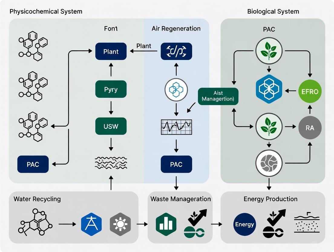
Integrated System Architecture and Workflows
A functional BLSS requires the tight integration of biological and physicochemical components. The following diagram illustrates the core material flows and subsystem interactions within an advanced BLSS, synthesizing concepts from the Lunar Palace and MELiSSA architectures.
Diagram: Material flow in a bioregenerative life support system.
Protocol: Integrated System Operation and Monitoring
Objective: To maintain stable atmospheric gas concentrations and material flow within a closed-loop BLSS during long-term operation with crew rotations.
Workflow:
- Atmospheric Monitoring: Continuously monitor concentrations of O₂, CO₂, and trace contaminants using in-situ sensors. Data is logged in real-time for trend analysis [16].
- Gas Balance Intervention:
- During Plant Dark Cycle: Implement physicochemical backup systems (e.g., CO₂ scrubbers, O₂ tanks) to compensate for the cessation of photosynthetic O₂ production and CO₂ consumption in plant cabins during their dark period [16].
- During Crew Shift Change: Anticipate and manage metabolic load changes as crew members enter or exit the closed environment. This may involve pre-emptive adjustment of plant growth chamber lighting schedules or deployment of physicochemical systems to buffer the transition [16].
- Water Loop Management: Treat and separate water streams based on source and contamination level (condensate, urine, hygienic water). Purified water is recursively allocated for human consumption, plant irrigation, and other processes [16].
- Failure Mode Monitoring: Record the number and time of failures for each technical unit (e.g., THCU, WTU). Use this data, in conjunction with methods like Monte Carlo simulation, to estimate system reliability and lifetime [15].
The Scientist's Toolkit: Key Research Reagents and Materials
The experimental research and technological development of BLSS rely on a suite of critical reagents, biological agents, and growth substrates.
Table 2: Essential Research Materials for BLSS Experimentation
| Item | Function / Rationale | Example Application |
|---|---|---|
| Hydroponic/Aeroponic Systems | Soilless plant cultivation; allows for precise control of nutrient delivery and root zone environment [12]. | Core plant growth methodology in CELSS and Lunar Palace [12] [16]. |
| LED Light Source Systems | Provides photosynthetically active radiation (PAR) for plant growth; enables control over photoperiod, light intensity, and spectrum to optimize yield and energy efficiency [15] [16]. | Used in the LED Light Source Unit (LLSU) of Lunar Palace 1 [15]. |
| Soil-Like Substrate (SLS) | A growth medium produced from bioconversion of solid organic wastes (inedible biomass, human feces); mimics the complex physical and nutrient-holding properties of soil [16]. | Created via fermentation in Lunar Palace to support plant growth in the Plant Cultivation Substrate Unit [16]. |
| Selected Cyanobacteria & Algae | Potential candidates for air revitalization (O₂ production, CO₂ consumption) and as a supplemental food source due to high protein content and rapid growth [12]. | Investigated in the NASA CELSS program and the European MELiSSA project [12] [13]. |
| Yellow Mealworms (Tenebrio molitor) | A micro-livestock agent for animal protein production; efficiently converts inedible plant biomass (e.g., straw) into high-quality protein for crew consumption [16]. | Integrated into the Solid Waste Treatment unit of Lunar Palace 1 [15] [16]. |
| Lunar Regolith Simulant | A terrestrial geological material engineered to mimic the chemical and physical properties of lunar soil. Essential for testing in-situ resource utilization (ISRU) strategies for plant cultivation and construction [18]. | Used in research for lunar agriculture and excavation technologies [18]. |
Quantitative Reliability Analysis Protocol
Objective: To quantitatively estimate the reliability and lifetime of a BLSS based on empirical unit failure data from long-duration missions.
Methodology (Based on Lunar Palace 370-day Experiment):
- Data Collection: Accurately record the number and precise time of failure for each operational unit within the BLSS (e.g., THCU, WTU, LLSU) over the entire experimental duration [15].
- Parameter Estimation: For each unit, model the failure as a stochastic process. Use maximum likelihood estimates to identify the failure rate (λ, in days⁻¹) and its 95% confidence interval based on the experimental data [15].
- Monte Carlo Simulation: Generate a large number of synthetic BLSS lifetime simulations (e.g., 50,000 runs). In each simulation, the time-to-failure for each unit is randomly generated based on its specific failure rate probability distribution [15].
- Lifetime Calculation: The overall system failure time in each simulation is defined as the moment the first critical unit fails. The average lifespan and confidence intervals for the entire BLSS are then calculated from the aggregated results of all simulation runs [15].
Results from Application: Application of this protocol to Lunar Palace 1 data yielded an estimated average BLSS lifespan of 19,112 days (approximately 52.4 years), with a 95% confidence interval of [17,367, 20,673] days. The analysis identified that the Temperature and Humidity Control Unit (THCU) and Water Treatment Unit (WTU) had the highest probability of failure and the greatest impact on overall system reliability [15].
The historical trajectory from NASA's CELSS to the international MELiSSA consortium and China's Lunar Palace demonstrates a convergent understanding that bioregenerative technologies are indispensable for sustained human presence beyond Earth. The experimental protocols and quantitative data generated, particularly from the long-duration Lunar Palace 365 mission, provide an invaluable empirical foundation for future system design. Key research gaps remain, including the full integration of biological and physicochemical subsystems into a seamless, fault-tolerant architecture, and a deeper understanding of the long-term effects of deep space radiation on all biological components of the BLSS [11]. Addressing these challenges through continued international research and development is a strategic imperative for the future of human space exploration.
The development of robust Life Support Systems (LSS) for long-duration space missions necessitates the precise quantification of core human metabolic requirements. Successful integration of physicochemical and biological subsystems depends on accurate data for oxygen consumption, water utilization, and nutritional needs. This document provides consolidated quantitative data, experimental protocols, and research tools essential for advancing closed-loop life support systems, drawing from current research in human performance and bioregenerative technologies.
Quantitative Data on Core Metabolic Requirements
The following tables summarize the fundamental quantitative requirements for human metabolism, essential for the design and sizing of life support systems.
Table 1: Daily Human Metabolic Input and Output Mass Balance [19]
| Parameter | Average Value per Person | Notes |
|---|---|---|
| Oxygen Consumption | 0.869 kg | For baseline human metabolism; increases with activity. |
| Water Consumption | 2.0 - 5.0 kg | Includes drinking and sanitary-hygiene purposes. |
| Caloric Intake | Varies | Based on a sustained energy expenditure of ~2.4 x BMR [20]. |
| Carbon Dioxide Production | 1.0 kg | Requires active removal from the atmosphere. |
| Solid & Liquid Wastes | Variable | Source of minerals for recycling; requires processing. |
Table 2: Performance of Biological Life Support System (BLSS) Components [19]
| Component | Function | Key Performance Metric | Notes |
|---|---|---|---|
| Microalgal Compartment | O₂ Production, CO₂ Assimilation | 0.60 kg dry weight/day | Produces ~0.869 kg O₂ by utilizing 1.0 kg of CO₂. |
| Higher Plant Compartment | O₂ Production, Food Production, Water Transpiration | 20-30 m² cultivation area/person | Provides food and a portion of O₂; transpiration moisture is a water source. |
| Soil-Like Substrate (SLS) | Inedible Biomass & Waste Processing | N/A | Processes plant residues and human wastes, releasing CO₂ and minerals. |
Table 3: Human Brain Metabolic Water Production from Glucose Catabolism [21]
| Metabolic State | Predicted Net Metabolic Water Production | Key Metabolic Shifts |
|---|---|---|
| Rest | Highest | Dominated by glucose oxidation in neuronal mitochondria. |
| Increased Activity | Reduced by 30-40% | Shift to glycolysis and ATP hydrolysis (consumes water). |
| Deep Sleep | Reduced by 30-40% | Associated with lower metabolic activity. |
Experimental Protocols
Protocol for Determining Sustained Metabolic Ceiling
Title: Quantification of Long-Term Human Energy Expenditure Capacity
Background: The human body exhibits a maximum sustained energy expenditure, or "metabolic ceiling," critical for designing food provision systems in isolated environments [20].
Methodology:
- Subject Population: Recruit elite endurance athletes undergoing prolonged training regimens (e.g., 30 weeks or more).
- Energy Expenditure Measurement: Utilize the doubly labeled water method to track total energy expenditure over extended periods.
- Basal Metabolic Rate (BMR) Calculation: Measure or calculate the BMR for each subject.
- Data Analysis: Calculate the ratio of total energy expenditure to BMR. The sustained ceiling is identified as the maximum observed ratio across the subject population over the study duration.
Expected Outcome: The study will confirm a sustained metabolic ceiling of approximately 2.4 times the Basal Metabolic Rate (BMR), beyond which the body unconsciously reduces energy expenditure in other physiological areas [20].
Protocol for Measuring Metabolic Water Flux in the Brain
Title: Stoichiometric Budgeting of Metabolic Water in the Rodent Brain
Background: Metabolic water is a significant contributor to brain fluid homeostasis, with production rates varying by functional state [21].
Methodology:
- Data Acquisition: Obtain published data on brain oxygen and glucose consumption rates in awake rodents (or humans) at rest, during elevated activity, and during sleep.
- Stoichiometric Modeling: Apply mechanistic stoichiometry to known biochemical pathways (glucose oxidation, glycolysis, glycogenolysis, ATP hydrolysis) to calculate the net production or consumption of water molecules for each pathway.
- Glucose Oxidation: Modeled as the primary source at rest.
- Glycolysis & ATP Hydrolysis: Account for water consumption during increased activity.
- Glycogenolysis: Model as a potential contributor during astrocyte activation.
- State-Dependent Budgeting: Integrate pathway fluxes to generate a comprehensive water budget for each brain state (rest, activity, sleep).
Expected Outcome: The protocol will yield quantitative predictions showing metabolic water production is highest at rest, dominated by neuronal mitochondria, and decreases by 30-40% during periods of increased activity or deep sleep [21].
Protocol for Algal and Higher Plant Integration in BLSS
Title: Phased Transfer of Regenerative Functions from Algae to Higher Plants
Background: A BLSS can be initiated with microalgae for rapid air and water revitalization, with a gradual transition to higher plants for more sustainable food and oxygen production [19].
Methodology:
- System Startup:
- Inoculate and activate the microalgal compartment to achieve target biomass density.
- The algal compartment is sized to fully satisfy one human's oxygen demand (utilizing 1.0 kg CO₂ and producing 0.869 kg O₂ per day).
- Higher Plant Compartment Establishment:
- Simultaneously, initiate a crop conveyor system (e.g., in a Soil-Like Substrate) with species selected for the mission diet.
- Note: The plant compartment requires 3-4 months to reach full food production efficiency and ~2 months for full oxygen/water regeneration.
- System Transition & Balancing:
- As the higher plant compartment matures, systematically reduce the operational load on the algal compartment.
- Continuously monitor and balance O₂/CO₂ levels, water vapor, and nutrient flows (N, P, K, S) between all subsystems.
- Waste Stream Integration:
- Implement physicochemical (e.g., "wet incineration" with H₂O₂) or biological units to process human wastes and inedible plant biomass.
- Reintegrate recovered minerals and CO₂ into the algal and plant compartments.
Expected Outcome: This protocol enables the establishment of a partially closed-loop system, defining the mass flows and time parameters required for a stable transition from a microalgae-dependent system to one dominated by higher plants [19].
System Workflow and Metabolic Pathways
BLSS Mass Flow Diagram
Brain Metabolic Water Pathways
The Scientist's Toolkit: Research Reagent Solutions
Table 4: Essential Materials for BLSS and Metabolic Research
| Item | Function/Application |
|---|---|
| Soil-Like Substrate (SLS) | A growth medium for higher plants that also processes inedible plant biomass and solid wastes, facilitating nutrient recycling within the BLSS [19]. |
| Microalgal Cultures (e.g., Chlorella) | The core biological component for initial air (O₂ production, CO₂ removal) and water revitalization; can be cultured in processed liquid waste streams [19]. |
| Liquid-Phase Oxidation Reactor (H₂O₂) | A physicochemical unit for the "wet incineration" of human wastes and inedible biomass, breaking them down into mineral nutrients that can be recycled to algal and plant compartments [19]. |
| Doubly Labeled Water (²H₂¹⁸O) | The gold-standard non-invasive method for measuring total energy expenditure in free-living humans over extended periods, crucial for validating metabolic models [20]. |
| Stoichiometric Metabolic Models | Computational frameworks for predicting inputs, outputs, and yields of biological processes (e.g., metabolic water production, O₂/CO₂ exchange) based on biochemical first principles [21]. |
Strategic Gaps and Geopolitical Landscape in Bioregenerative Technology Development
The pursuit of long-duration human space exploration is fundamentally constrained by the trinity of logistics costs, technological limits, and human health risks associated with current physical/chemical (physicochemical) life support systems [8]. Bioregenerative Life Support Systems (BLSS) represent a paradigm shift, utilizing biological organisms to recycle waste, regenerate atmosphere, and produce food, thereby enabling greater self-sufficiency for missions beyond low-Earth orbit (LEO) [5]. The geopolitical landscape of this technology is marked by a significant strategic divergence. Following the 2004 Exploration Systems Architecture Study (ESAS), NASA discontinued and physically demolished programs like BIO-PLEX, leading to critical gaps in US capabilities [8] [22]. Conversely, the China National Space Administration (CNSA) has "embraced and advanced" these same technologies over the past two decades, successfully demonstrating a closed-system life support in the Beijing Lunar Palace (Lunar Palace 1) that sustained a crew of four for a full year [8] [22]. This paper analyzes these strategic gaps and provides detailed application notes and protocols to guide the integration of bioregenerative and physicochemical systems.
Current Landscape and Geopolitical Dynamics
Comparative Analysis of International BLSS Programs
The global development of BLSS has followed distinct paths, resulting in varied levels of technological maturity and integration.
Table 1: Comparison of Major International BLSS Initiatives and Capabilities
| Program / Agency | Key Focus & Technologies | Integration Level & Human Testing | Notable Achievements |
|---|---|---|---|
| NASA (Historical: CELSS, BIO-PLEX) | Controlled Environment Agriculture (CEA), higher plant cultivation [8] | Formerly integrated habitat testing; program discontinued in 2004 [8] | Pioneering research; foundational work adopted by other nations [8] |
| CNSA (Lunar Palace 1) | Integrated "human-plant-animal-microbe" system [22] | High; ground-based, fully integrated testing with human crews [8] [22] | 370-day continuous operation with a crew of four; high system stability [22] |
| ESA (MELiSSA) | Compartmentalized, engineered ecosystem mimicking a lake [3] | Moderate; advanced component testing, but no closed-system human testing [8] [3] | Long-running, systematic engineering program; pilot plant (MPP) operation [5] [3] |
| Roscosmos (BIOS-3) | Closed ecological systems with algae and plants [5] | High; historical human-in-the-loop testing in the 20th century [5] | Early demonstrations of closed gas and water exchange [5] |
The data reveals that CNSA currently leads in demonstrating fully integrated, crew-tested BLSS operations. The Lunar Palace 1 facility achieved a world record for continuous operation, with its four-component biological chain maintaining stable interactions and plant production efficiency fully meeting crew demand [22]. This capability is a cornerstone of China's plans for long-term lunar habitation. Meanwhile, NASA's current approach remains reliant on resupply missions for food, water, and consumables for its physicochemical Environmental Control and Life Support Systems (ECLSS), a model that is logistically and economically prohibitive for sustained lunar or Martian presence [8] [6]. The European MELiSSA program offers a robust, engineering-focused pathway but has not yet reached the integrated human-testing stage [8] [3].
Quantitative Analysis of Life Support Requirements
A systems-level understanding of human metabolic needs is fundamental to BLSS design. These requirements dictate the scale and performance of all downstream biological and physicochemical components.
Table 2: Daily Metabolic Mass Balance for a Reference Astronaut (82 kg) [6]
| Consumable Input | Mass (kg) | Waste Output | Mass (kg) |
|---|---|---|---|
| Oxygen (O₂) | 0.89 | Carbon Dioxide (CO₂) | 1.08 |
| Food (Dry Mass) | 0.80 | Respired & Perspired Water | 3.04 |
| Drinking Water | 2.79 | Urine | 1.40 |
| Food Preparation Water | 0.50 | Feces | 0.09 |
| Water in Food | 0.76 | ||
| TOTAL INPUT | 5.74 | TOTAL OUTPUT | 5.61 |
For a crew of four on a 3-year mission, these daily requirements translate into a prohibitive payload mass of over 25,000 kg for food and water alone, underscoring the non-viability of a pure resupply strategy [3]. A BLSS aims to close these mass loops, with a particular focus on nitrogen recovery, as 85% of the recoverable nitrogen in a habitat is found in urine, primarily as urea [3].
Critical Gaps and Integrated System Requirements
The transition from current ECLSS to a hybrid BLSS-ECLSS architecture is hindered by several strategic gaps identified in recent analyses:
- Nitrogen Recovery and Urine Processing: Current ISS systems, like the Urine Processor Assembly (UPA), acidify and chemically stabilize urine to prevent scaling and urea hydrolysis, subsequently removing water via distillation. The resulting brine, rich in nitrogen and other nutrients, is considered waste [3]. A BLSS requires technologies to recover this nitrogen in a bioavailable form (e.g., nitrate) for plant and algal production [3].
- Crop System Integration and Optimization: Not all plants are equally suitable for space. Mission scenarios dictate crop selection: short-duration missions benefit from fast-growing, high-nutrition leafy greens and microgreens, while long-duration outposts require staple crops (wheat, potato) for carbohydrates and proteins [5]. Gaps exist in understanding the Edible Biomass Yield and resource requirements (light, water, nutrients) of these crops in closed, space-relevant environments [4].
- Radiation Effects on Biological Systems: A critical knowledge gap exists regarding the impact of deep-space radiation on the efficiency and stability of biological components, including plants and microorganisms essential for BLSS function [8].
- Integrated Pest Management (IPM): As BLSS modules scale, the risk of phytopathogen outbreaks increases, as demonstrated by a Fusarium oxysporum outbreak on Zinnia plants in an ISS Veggie module [23]. A comprehensive, preventive IPM protocol for space-based agriculture is underdeveloped [23].
Application Notes & Protocols
This section provides detailed methodologies for bridging the identified gaps through integrated research.
Protocol: Nitrogen Recovery from Urine for Fertilizer Production
This protocol outlines the integration of a biological nitrogen recovery process with the existing physicochemical UPA, targeting the conversion of urea and ammonium into nitrate for plant nutrition.
1.0 Principle: Utilize a two-stage microbial process to convert urea and ammonia in urine to nitrate. Ureolytic bacteria first hydrolyze urea to ammonia and carbon dioxide. Subsequently, nitrifying bacteria (Nitrosomonas and Nitrobacter spp.) sequentially oxidize ammonia to nitrite and then to nitrate [3].
2.0 Workflow Diagram: Nitrogen Recovery Process
3.0 Reagents and Equipment:
- Stabilized Urine Brine: Simulant or real effluent from a UPA-like system.
- Microbial Inocula: Pure or enriched cultures of Bacillus spp. (ureolytic), Nitrosomonas europaea, and Nitrobacter winogradskyi.
- Bioreactor System: Two continuously stirred tank reactors (CSTRs) with pH, temperature, and dissolved oxygen control.
- Analytical Equipment: Ion Chromatography system for NH₄⁺, NO₂⁻, NO₃⁻ quantification; HPLC for urea analysis.
4.0 Procedure:
- Feedstock Preparation: Adjust the pH of the stabilized urine brine to 7.5 using a sterile NaOH solution.
- Stage 1 - Ureolysis: Feed the pH-adjusted brine into the first CSTR inoculated with ureolytic bacteria. Maintain temperature at 30°C and monitor urea concentration until hydrolysis is >95% complete.
- Stage 2 - Nitrification: Transfer the effluent from Stage 1 to the second CSTR, inoculated with nitrifying bacteria. Maintain dissolved oxygen >4 mg/L and temperature at 28-30°C. Monitor the conversion of NH₄⁺ to NO₃⁻ until [NH₄⁺] is below a target threshold (e.g., <5 mg/L).
- Harvesting: Pass the nitrified effluent through a centrifuge to remove microbial biomass. Sterilize the supernatant via 0.2 µm filtration. The resulting solution is a liquid fertilizer ready for integration into hydroponic systems.
Protocol for BLSS Crop Selection and Cultivation
1.0 Principle: Select plant species based on mission duration and objectives to optimize resource use and meet nutritional needs. Use controlled environment agriculture (CEA) techniques with 100% nutrient recycling from BLSS loops [5].
2.0 Workflow Diagram: BLSS Crop Cultivation Logic
3.0 The Scientist's Toolkit: Key Research Reagents & Materials
Table 3: Essential Reagents for BLSS Crop and Microbiology Research
| Reagent / Material | Function & Application in BLSS Research |
|---|---|
| Cyanobacteria (e.g., Anabaena sp.) | Versatile organisms for Stage 1 regolith bioweathering, O₂ production, CO₂ fixation, and nutritional biomass production [6]. |
| Nitrifying Bacteria Consortia | Essential for converting ammonia from waste streams into nitrate, the primary nitrogen fertilizer for plants [3]. |
| Hydroponic Nutrient Solution | A precisely formulated aqueous solution of all essential mineral nutrients for plant growth, to be derived from recycled waste streams [5]. |
| Select Plant Cultivars | Short-Term: Lettuce, kale, microgreens (fast, high-nutrition). Long-Term: Wheat, potato, soybean, tomato (carbohydrates, protein) [5]. |
| LED Lighting Systems | Provides specific, energy-efficient light spectra (e.g., red, blue, white) to optimize plant photosynthesis and morphology [4]. |
4.0 Procedure:
- Species Selection: Based on the mission class defined in the logic diagram, select appropriate species from the toolkit.
- Growth System Setup: Establish a hydroponic or aeroponic system. Circulate the nitrate-rich fertilizer from Protocol 4.1.
- Environmental Control: Maintain optimal conditions: LED photoperiod of 16-18 hours, light intensity of 300-600 µmol/m²/s photosynthetic photon flux density (PPFD), relative humidity of 60-70%, and CO₂ concentration of 1000-1200 ppm.
- Monitoring and Harvest: Monitor plant health, growth rates, and gas exchange (O₂ production/CO₂ consumption). At maturity, harvest edible biomass and return inedible plant waste to the BLSS recycling loop (e.g., for composting or microbial processing).
Integrated Pest Management (IPM) Protocol for BLSS
1.0 Principle: Implement a dynamic, multi-layered strategy to prevent, monitor, and control pest and pathogen outbreaks in space-based plant growth systems [23].
2.0 Procedure:
- Prevention (Primary):
- Quarantine & Sanitation: Strictly quarantine and surface-sterilize all seeds and plant materials before introduction into the BLSS.
- System Design: Utilize semi-closed plant growth modules with independent environmental controls (e.g., Advanced Plant Habitat) to isolate crops from the crew habitat microbiome [23].
- Environmental Control: Avoid conditions of high humidity and free water on plant surfaces, which are conducive to pathogen growth [23].
- Monitoring:
- Conduct daily visual inspections of plants for disease symptoms or insect pests.
- Utilize molecular tools (e.g., PCR) and culture-based methods to regularly assay for the presence of key phytopathogens in the air, water, and on plant surfaces.
- Control:
- Physical: Remove and isolate infected plant material immediately. Use HEPA filtration for intake air in open systems like Veggie.
- Biological: Apply approved microbial antifungals or biopesticides. The use of beneficial microbes as biocontrol agents requires further research for spaceflight approval.
- Chemical: The use of conventional pesticides is a last resort due to risks of contaminating closed-loop systems and affecting crew health.
The strategic gap in bioregenerative life support technology between the US and its competitors, notably China, poses a significant risk to the sustainability and leadership of future lunar and Martian exploration programs [8] [22]. Closing this gap requires a committed, long-term strategy that moves beyond pure physicochemical systems. The application notes and protocols detailed herein provide a roadmap for the necessary integration of biological systems—focusing on critical path technologies like nitrogen recovery, optimized crop production, and proactive pest management. The success of future "endurance-class" deep space missions will depend on achieving the high degree of self-sufficiency that only a fully developed and flight-proven hybrid BLSS-ECLSS can provide.
Implementing Hybrid Systems: Methodologies for Air, Water, and Food Production
The advancement of human space exploration beyond low-Earth orbit is contingent upon the development of robust, self-sustaining life support systems. This application note details the integration of physicochemical (PC) and biological technologies to create a hybrid air revitalization system. The outlined architecture synergistically combines carbon dioxide (CO₂) capture, its chemical reduction via the Sabatier process, and biological oxygen (O₂) production using cyanobacteria for long-duration missions. We provide a comprehensive technical overview, quantitative performance data, detailed experimental protocols for key processes, and a catalog of essential research reagents to support ground-based testing and development of these integrated systems.
Future long-duration missions to the Moon and Mars cannot rely on the current paradigm of resupply from Earth due to the excessive mass of essential consumables, estimated at 15–20 kg per person per day [24]. Air revitalization—the process of maintaining a breathable atmosphere by removing CO₂ and replenishing O₂—is a cornerstone of any life support system. While the International Space Station (ISS) employs primarily physicochemical (PC) systems, Bioregenerative Life Support Systems (BLSS) offer the potential for greater closure of air, water, and food loops [4] [8].
This document frames a hybrid approach within the broader thesis that the synergistic integration of PC and biological systems is the most viable path toward sustainable, long-duration space habitation. The proposed system leverages the reliability of PC components for initial CO₂ processing and the regenerative capacity of biological components, specifically cyanobacteria, for O₂ production and biomass generation. This architecture is exemplified by the three-stage reactor system proposed for planetary habitats, which integrates regolith processing, atmospheric revitalization, and biofuel production [6].
Table 1: Daily Metabolic Requirements and Outputs for a Reference Astronaut [6]
| Consumable | Input (kg/day) | Waste Product | Output (kg/day) |
|---|---|---|---|
| Oxygen (O₂) | 0.89 | Carbon Dioxide (CO₂) | 1.08 |
| Food (Dry Mass) | 0.80 | Urine & Feces | (See Water) |
| Drinking Water | 2.79 | Resp. & Perspiration Water | 3.04 |
| Food Prep Water | 0.50 | Urine | 1.40 |
| Water in Food | 0.76 | Feces | 0.09 |
| Total (Approx.) | ~5.84 | Total (Approx.) | ~4.53 |
Core System Components and Technologies
Physicochemical (PC) Subsystem: CO₂ Capture and Sabatier Reaction
The PC subsystem handles the initial concentration and processing of CO₂ from the cabin atmosphere.
- CO₂ Capture: Current systems on the ISS use molecular sieves and adsorption beds to concentrate CO₂ from the cabin air [6].
- Sabatier Reactor: The concentrated CO₂ is then reacted with hydrogen (H₂) in a catalytic (typically ruthenium or nickel-based) reactor. The primary reaction is: CO₂ + 4H₂ → CH₄ + 2H₂O + Energy This process effectively removes CO₂, produces water (a valuable resource), and methane (CH₄) [6]. The methane can be vented, used as a propellant, or, in advanced concepts, serve as a feedstock for other biological processes [6].
Biological Subsystem: Cyanobacteria-Based Oxygen Production
The biological component completes the air loop by regenerating O₂ from CO₂. Cyanobacteria, particularly Limnospira indica (formerly Arthrospira or Spirulina), are ideal candidates due to their high photosynthetic efficiency, edibility, and resilience.
- Organism: Limnospira indica, as used in the European Space Agency's MELiSSA (Micro-Ecological Life Support System Alternative) project [24].
- Function: In a photobioreactor (PBR), cyanobacteria consume CO₂ and, using light energy, perform photosynthesis: CO₂ + H₂O + Light → Biomass + O₂ This process directly revitalizes the cabin atmosphere by producing breathable O₂ while simultaneously generating nutritious biomass [6] [24].
System Integration Logic
The synergy between the PC and biological subsystems creates a more resilient and regenerative whole. The Sabatier process efficiently removes the bulk of CO₂ and produces water, while the cyanobacteria fine-tune the O₂ level and produce food. An integrated system can also explore using biological components to further process waste streams, such as using non-nitrified urine as a nitrogen source for cyanobacteria [24].
Diagram 1: Integrated air revitalization system logic flow.
Experimental Protocols for System Validation
This protocol is adapted from ground demonstration studies for the MELiSSA loop [24] and investigates the viability of using simplified waste streams.
1. Objective: To cultivate Limnospira indica using different nitrogen sources (nitrate, urea, ammonium) representative of non-nitrified human urine and to monitor its effect on biomass growth and oxygen production capacity in a closed-loop system.
2. Materials:
- Limnospira indica (e.g., PCC 8005 strain) inoculum.
- Modified Zarrouk’s medium (lacking nitrate, for experimental setups).
- Nitrogen sources: Sodium Nitrate (NaNO₃), Urea ((NH₂)₂CO), Ammonium Chloride (NH₄Cl).
- Photobioreactor (PBR) system with lighting control, temperature control, pH and dissolved O₂ probes.
- Gas mixing system to supply a defined CO₂-in-air mixture.
- Oxygen sensor for monitoring headspace O₂ concentration.
- Mouse compartment or equivalent CO₂ source (e.g., calibrated gas flow).
3. Methodology:
- Preparation: Set up three independent PBR systems. Prepare growth media for each condition: 1) Nitrate-based (control), 2) Urea-based, 3) Ammonium-based. Ensure equivalent molar nitrogen concentration across all media.
- Inoculation: Aseptically inoculate each PBR with a standardized volume of a healthy Limnospira culture to an initial optical density (OD₅₆₀) of ~0.1.
- System Closure & Control: Connect the PBRs to the CO₂ source. Implement a deterministic control law that modulates the incident light intensity on the PBR based on the real-time O₂ concentration in the loop. The setpoint should be 20.3% O₂ [24].
- Monitoring: Conduct the experiment for 35 days. Monitor and record daily:
- O₂ and CO₂ concentrations in the gas loop.
- Incident light intensity (as controlled by the algorithm).
- Culture OD₅₆₀ and pH.
- Harvesting & Analysis: At the end of the experiment, harvest biomass for biochemical analysis (e.g., protein, pigment content).
4. Anticipated Results: The system with nitrate and urea is expected to maintain the O₂ setpoint of 20.3%, while the ammonium-based system may struggle, potentially reaching a maximum of only 19.5% O₂, indicating inhibition or reduced photosynthetic efficiency [24].
Diagram 2: Cyanobacteria O2 production experimental workflow.
Protocol: Integrated Sabatier-BLSS Performance Testing
This protocol outlines a test for evaluating the interface and mass balance between a Sabatier reactor and a cyanobacteria PBR.
1. Objective: To characterize the gas exchange and resource recovery when diverting a variable fraction of the crew's CO₂ output from the Sabatier reactor to a cyanobacteria PBR.
2. Materials:
- Sabatier reactor engineering model.
- Limnospira indica PBR system.
- Mass Flow Controllers (MFCs) for CO₂, H₂, and air.
- Gas analyzers for O₂, CO₂, and CH₄.
- Water collection and measurement apparatus.
3. Methodology:
- Baseline PC Operation: Operate the Sabatier reactor with a simulated crew CO₂ input (e.g., 3.24 kg/day for a 3-person crew [6]) and stoichiometric H₂. Measure CO₂ conversion efficiency, CH₄ production, and water recovery.
- Integrated Operation: Divert a fraction (e.g., 10%, 25%, 50%) of the incoming CO₂ stream to the PBR. Ensure the Sabatier reactor's H₂ input is adjusted accordingly.
- Monitoring: Monitor both systems for 14 days. Record:
- Input and output gas compositions for both units.
- Water produced by the Sabatier reactor.
- O₂ production rate from the PBR.
- Biomass accumulation rate in the PBR.
4. Data Analysis: Calculate the overall system closure for carbon and oxygen. Determine the optimal CO₂ split ratio that maximizes O₂ production and water recovery while maintaining safe CO₂ levels in the simulated cabin atmosphere.
The Scientist's Toolkit: Key Research Reagents and Materials
Table 2: Essential Materials for BLSS and PC Life Support Research
| Item Name | Function/Application | Example/Notes |
|---|---|---|
| Limnospira indica | Model cyanobacterium for O₂ production, CO₂ sequestration, and biomass. | PCC 8005 strain; used in ESA's MELiSSA project [24]. |
| Zarrouk's Medium | Standardized growth medium for Limnospira cultivation. | Can be modified to use different nitrogen sources (NO₃⁻, Urea, NH₄⁺) [24]. |
| Photobioreactor (PBR) | Controlled environment for cultivating photosynthetic organisms. | Requires integrated lighting, pH/DO/temperature sensors, and gas exchange capabilities [6] [24]. |
| Sabatier Reactor | Converts CO₂ and H₂ into methane and water. | Uses a ruthenium or nickel-based catalyst [6]. |
| Mass Spectrometer | Speciated, real-time monitoring of volatile organic compounds (VOCs) and gases. | e.g., SIFT-MS or PTR-ToF-MS; for trace gas analysis [25]. |
| Automated Gas Chromatograph (Auto-GC) | Periodic, high-precision analysis of gas composition. | Used for community air monitoring; can be adapted for cabin air [25]. |
| Nitrogen Sources | Simulating waste streams for cyanobacterial cultivation. | Sodium Nitrate (control), Urea, Ammonium Chloride [24]. |
The integration of CO₂ capture, Sabatier reactors, and cyanobacteria-based oxygen production represents a promising hybrid architecture for future life support systems. The quantitative data and experimental protocols provided herein offer a foundation for researchers to validate and advance this technology. Ground demonstration projects, such as those conducted for the MELiSSA loop, are critical de-risking steps on the path to deploying these systems for sustained human exploration of the Moon and Mars. Future work must focus on closing the water and nutrient loops further by integrating higher plants and refining the control systems for these complex, synergetic ecosystems [4] [8].
The integration of physiochemical and biological systems is paramount for advancing closed-loop life support for long-duration space missions. Current physiochemical systems, like the urine processor assembly (UPA) on the International Space Station (ISS), recover over 90% of water but leave concentrated brines containing valuable nutrients [26]. This application note details protocols for coupling the UPA with downstream biological processes to recover these nutrients, transforming waste into a resource for bioregenerative life support systems (BLSS). This hybrid approach is a critical step toward the logistical biosustainability required for future lunar bases and Mars missions [11] [27].
Performance Data and System Comparison
Table 1: Performance Metrics of Urine Processing Technologies
| Technology / System | Primary Function | Water Recovery Rate | Nutrient Output/Handling | Technology Readiness Level |
|---|---|---|---|---|
| ISS Urine Processor Assembly (UPA) [26] | Water recovery from urine via distillation | ~75% from urine | Produces a nutrient-rich brine effluent | Operational on ISS |
| ISS Brine Processor Assembly (BPA) [26] | Further water extraction from UPA brine | Increases overall system recovery to 98% | Produces a dry, solid nutrient concentrate | Operational on ISS |
| Brine Integrator | Manages BPA output for nutrient recycling | N/A | Conditions solid brine for biological processing | Conceptual / Prototype |
| Microbial Electrochemical Systems [28] | Nutrient recovery and fertilizer production from source-separated urine | N/A | Can generate nitrogen-rich liquid fertilizers | Lab-scale research |
| Struvite Precipitation [28] | Phosphorus recovery from urine | N/A | Produces Struvite (magnesium ammonium phosphate) fertilizer | Pilot-scale demonstrations |
| Pine Bark (PB) Ash Filtration [29] | Nutrient recovery and solid fertilizer production via dehydration | N/A | Produces a solid fertiliser with 9.7% N, 1.5% P, 8.4% K | Lab-scale research |
Table 2: Analysis of Recovered Urine-Derived Fertilizers
| Fertilizer Product | Key Nutrients | Reported Efficacy vs. Commercial Fertilizer | Production Method |
|---|---|---|---|
| Struvite [28] | Phosphorus (P), Nitrogen (N) | N/A | Physiochemical Precipitation |
| Calcium Phosphate [28] | Phosphorus (P) | N/A | Physiochemical Precipitation |
| Ammonium Sulphate [28] | Nitrogen (N) | N/A | Membrane Processes, Physiochemical |
| Nutrient-Rich Liquid [28] | N, P, K | N/A | Microbial Electrochemical, Hybrid Systems |
| Pine Bark Ash Product [29] | N, P, K | Superior N and P uptake by ryegrass and maize; better growth in weight and size of basil plants. | Dehydration with pine bark ash media |
| Solid Fertiliser (N, P, K, NaCl, KCl) [28] | N, P, K, Sodium (Na), Chlorine (Cl) | N/A | Integrated/Treatment Trains |
Experimental Protocols
Protocol A: Conditioning Brine Processor Assembly (BPA) Effluent for Biological Processing
This protocol describes the preparation of the solid nutrient concentrate produced by a system analogous to the ISS BPA for use as a substrate in biological nutrient recovery.
I. Materials and Reagents
- Solid brine effluent from BPA
- Sterile, deionized water
- Reagent 1: Pine Bark Ash. Function: A high-pH (alkaline) filtration and conditioning media that enhances nitrogen retention and promotes the formation of stable fertilizer products during dehydration [29].
- Reagent 2: Calcium Hydroxide (Ca(OH)₂). Function: A chemical additive used to modify urine pH, inactivate the urease enzyme to prevent ammonia volatilization, and precipitate phosphorus into a recoverable solid form [28] [29].
- Analytical equipment: pH meter, analytical balance, magnetic stirrer
II. Methodology
- Solubilization: Precisely weigh 10 g of solid BPA effluent. Gradually add 100 mL of sterile, deionized water under constant stirring to create a concentrated nutrient solution.
- pH Adjustment and Conditioning: Adjust the pH of the solution. For subsequent dehydration, raise the pH to >10 using a calcium hydroxide solution or pine bark ash to suppress ammonia volatilization. For microbial processing, adjust the pH to a neutral range (6.5-7.5) as required.
- Filtration: Filter the conditioned solution using a vacuum filtration system with pine bark ash as a filter media to capture particulates and initiate nutrient adsorption [29].
- Product Formation: The filtered solution is ready for biological processing. The filter media itself, now enriched with nutrients, can be dehydrated to form a solid fertilizer product.
Protocol B: Biological Production of Urine-Derived Fertilizer Using Pine Bark Media
This protocol is adapted from recent research for creating a solid, urine-derived fertilizer using pine bark (PB) and its derivatives, simulating the use of BPA concentrate [29].
I. Materials and Reagents
- Source-separated human urine or synthetic BPA effluent solution (from Protocol A)
- Pine bark media: Feedstock (raw, ground), Biochar (pyrolyzed at 350°C and 650°C), and Ash (produced by heating feedstock at 750°C) [29]
- Dehydration ovens (45°C and 60°C)
- Glass containers with lids
II. Methodology
- Media Preparation: Weigh 50 g of the selected pine bark media (feedstock, biochar, or ash) into individual glass containers.
- Urine/Effluent Addition: Add the urine or BPA effluent solution to the media. Stir the mixture vigorously for 5 seconds to ensure full integration [29].
- Dehydration: Place the open containers in an oven pre-heated to either 45°C or 60°C. The dehydration process is complete when a solid, friable product is achieved.
- Curing and Storage: Periodically stir the mixture during dehydration to ensure even drying. Once dehydrated, the solid product is milled into a powder and stored in a sealed container for later agronomic testing.
III. Agronomic Efficacy Testing
- Soil Incubation: Apply the dehydrated product to a loam soil at a rate equivalent to 100 kg N per hectare. Incubate the soil at field capacity and 25°C [29].
- Nutrient Release Analysis: Conduct destructive sampling at days 0, 7, 14, 21, 28, 42, and 56. Analyze the soil for pH, ammonium-N, nitrate-N, and extractable P.
- Data Interpretation: Monitor the conversion of ammonium-N to nitrate-N. Products like pine bark ash dehydrated at 45°C have been shown to maintain high nitrate-N levels (~38 mg kg⁻¹), indicating efficient N recovery and release [29].
Process Visualization and Workflow
The following diagram illustrates the integrated workflow for managing urine and recovering water and nutrients, connecting the physiochemical hardware of the ISS with downstream biological processing methods.
Integrated Urine Processing Workflow
The Scientist's Toolkit: Key Research Reagents and Materials
Table 3: Essential Materials for Hybrid Life Support Research
| Material / Reagent | Function in Research |
|---|---|
| Pine Bark (PB) Feedstock [29] | An acidic (pH ~3.0) organic waste material used as a substrate to recover nutrients from urine via dehydration; its low pH helps suppress urease activity, reducing nitrogen loss. |
| PB Biochar [29] | A porous carbon-rich material produced by pyrolyzing pine bark. Used to absorb and retain nutrients from liquid waste, creating a carbon-rich solid fertilizer that improves soil fertility and carbon sequestration. |
| PB Ash [29] | A high-pH alkaline material used to modify urine pH, inactivate urease, and produce a nutrient-rich solid fertilizer product through dehydration. Demonstrated to be highly effective in increasing nitrogen availability. |
| Calcium Hydroxide (Ca(OH)₂) [28] [29] | A chemical reagent used for pH modification and phosphorus precipitation in urine, leading to the production of calcium phosphate fertilizers. |
| Artificial Human Urine (AHU) [29] | A standardized synthetic solution containing urea, uric acid, creatinine, and salts, used for controlled and reproducible experiments without the variability of real urine. |
| Struvite [28] | A crystalline fertilizer product (magnesium ammonium phosphate) recovered from urine, providing a slow-release source of phosphorus and nitrogen. |
The integration of robust food production systems is a critical component for the advancement of long-duration human space exploration and the development of closed-loop life support. These systems must optimize plant characterization and cultivation to achieve logistical biosustainability, reducing reliance on resupply missions from Earth [11]. Current approaches for human space habitation predominantly depend on physical/chemical-based Environmental Control and Life Support Systems (ECLSS), which face significant constraints from logistics costs, technological limits, and human health risks [11]. Bioregenerative Life Support Systems (BLSS), which utilize biological components like plants and microalgae, present a viable path toward creating self-sustaining habitats by regenerating air and water and producing food [11]. This document provides detailed application notes and protocols for the implementation and study of such systems, framed within the broader context of integrating physicochemical and biological research for advanced life support.
Effective planning for closed-environment food production requires a clear understanding of performance metrics and comparative technologies. The following tables summarize key quantitative data relevant to system design.
Table 1: Performance Metrics of Cultivation Technologies for Closed Environments
| Technology / Organism | Key Metric | Reported Value | Significance for Closed Systems |
|---|---|---|---|
| Microalgae (General) | CO₂ Fixation Efficiency | 10-50x higher than terrestrial plants [30] | Superior air revitalization potential. |
| Microalgae (Specific) | CO₂ Fixed per Biomass | 1.83 tons of CO₂ per ton of algal powder [30] | Enables precise mass balancing for atmosphere management. |
| Microalgae in Aquaculture | Carbon Emission Reduction | Potential to reduce emissions from 1.8 kg to 3.3 kg CO₂e/kg salmon [30] | Model for integrated, multi-trophic closed systems. |
| Precision Agriculture (UAV-based) | Phenotyping Data Acquisition | High-throughput, efficient, low-cost [31] | Platform for non-destructive, continuous plant characterization. |
Table 2: 2025 Sustainable Agriculture Trends with Relevance to Closed Systems [32]
| Trend | Estimated Adoption in 2025 | Potential Environmental Impact Reduction | Application to Closed Environments |
|---|---|---|---|
| Responsible Sourcing & Traceability | 62% | 35% | Model for supply chain integrity and input verification in BLSS. |
| Precision Agriculture Technologies | 55% | 28% | Directly applicable to resource optimization (water, nutrients, light) in controlled agriculture. |
| Biological Inputs / Green Chemistry | 39% | 22% | Reduces reliance on synthetic chemicals, aligning with closed-loop recycling. |
| Circular Economy & Waste Valorization | 33% | 16% | Core principle for BLSS; converting waste streams into resources. |
Experimental Protocols
Protocol: High-Throughput Plant Phenotyping Using Unmanned Aerial Vehicles (UAVs)
This protocol outlines a methodology for non-destructive, high-frequency monitoring of plant growth and health in controlled environments, adapted from field-based precision agriculture [31].
1. Objective: To acquire quantitative phenotypic data (e.g., plant height, Leaf Area Index (LAI), disease presence) rapidly and non-destructively for a large population of plants under controlled conditions.
2. Materials:
- Multirotor UAV platform.
- Multispectral or hyperspectral sensor.
- Ground control points (for spatial referencing).
- Data processing workstation with appropriate software (e.g., Python with computer vision libraries, specialized photogrammetry software).
3. Procedure:
- Step 1: Mission Planning. Define the flight path over the cultivation area to ensure complete coverage. Set flight altitude and image overlap (e.g., 80% front and side overlap) based on the required spatial resolution.
- Step 2: Sensor Calibration. Perform radiometric calibration of the multispectral sensor using a calibration panel to ensure data consistency across flights.
- Step 3: Data Acquisition. Conduct autonomous flights at regular intervals (e.g., daily or weekly). Ensure consistent lighting conditions, preferably using controlled growth chamber lighting to eliminate shadows.
- Step 4: Data Pre-processing. Use structure-from-motion (SfM) photogrammetry to generate orthomosaic images and digital surface models (DSM) from the captured imagery.
- Step 5: Phenotypic Trait Extraction.
- Plant Height: Calculate by subtracting a digital terrain model (DTM) of the growing medium surface from the DSM of the plant canopy [31].
- Leaf Area Index (LAI): Derive using vegetation indices (e.g., NDVI) from multispectral data, established through regression models with ground-truthed LAI measurements [31].
- Disease Detection: Utilize machine learning algorithms trained on annotated image datasets to identify and classify disease symptoms or nutrient stress patterns [31].
4. Data Analysis: Time-series analysis of extracted traits allows for the assessment of growth rates, response to environmental changes, and early detection of stressors.
Protocol: Integration of Microalgae for Carbon Capture and Recycling
This protocol details the use of microalgae photobioreactors (PBRs) within a closed system for atmospheric regeneration and biomass production, drawing from successful terrestrial analogs [33] [30].
1. Objective: To utilize microalgae for the capture of carbon dioxide from the habitation atmosphere and the production of valuable biomass for food, feed, or other applications.
2. Materials:
- Tubular or flat-panel photobioreactor (PBR) system.
- CO₂-rich gas stream (e.g., from crew respiration or ECLSS).
- Microalgae strain (e.g., Chlorella sp., Scenedesmus sp.).
- Nutrient medium (containing N, P, and micronutrients).
- Harvesting system (e.g., centrifuge, membrane filtration).
3. Procedure:
- Step 1: System Sterilization. Sterilize the PBR and all connecting tubing to prevent microbial contamination.
- Step 2: Inoculation. Inoculate the sterile PBR with a log-phase microalgae culture in a suitable nutrient medium.
- Step 3: Cultivation Operation.
- Continuously bubble the CO₂-rich gas stream (at a controlled concentration, e.g., 1-5%) through the culture.
- Maintain optimal temperature using a heating/cooling system integrated with the PBR [33].
- Provide continuous illumination with LED lights at wavelengths and intensities optimized for the algal species.
- Monitor culture density (optical density) and pH daily.
- Step 4: Harvesting. When the culture reaches stationary phase, initiate harvesting. Separate biomass from the liquid medium using centrifugation. The cleaned medium can be recycled.
- Step 5: Biomass Processing. The algal paste can be dried and processed into powder for incorporation into food or feed formulations [30].
4. Data Analysis: System performance is evaluated by calculating the CO₂ fixation rate (g CO₂/L culture/day) and biomass productivity (g biomass/L culture/day). The biomass should be analyzed for nutritional composition (protein, lipid, carbohydrate content).
System Workflow and Integration Diagrams
The following diagrams illustrate the logical workflow for plant phenotyping and the integration of biological and physicochemical systems within a closed habitat.
High-Throughput Phenotyping Workflow
Integrated Life Support System
The Scientist's Toolkit: Research Reagent Solutions
The following table details essential materials and reagents for establishing and maintaining advanced plant and microalgae cultivation systems for closed-environment research.
Table 3: Essential Research Reagents and Materials for Closed-Environment Cultivation
| Item | Function / Application | Example / Notes |
|---|---|---|
| Photobioreactor (PBR) | Controlled cultivation of microalgae; enables precise management of gas exchange, temperature, and light [33]. | Tubular or flat-panel designs with integrated temperature control and gas mixing systems. |
| Unmanned Aerial Vehicle (UAV) | Platform for high-throughput, non-destructive plant phenotyping in large growth chambers or greenhouses [31]. | Fitted with multispectral or hyperspectral sensors for capturing plant health data. |
| Multispectral/Hyperspectral Sensors | Measure reflected electromagnetic energy from plants; used to calculate vegetation indices (e.g., NDVI) correlating to plant health, biomass, and stress [31]. | Critical for quantifying phenotypic traits like Leaf Area Index (LAI) and detecting early stress. |
| Polydimethylsiloxane (PDMS) | A transparent, gas-permeable polymer used in microfluidic device fabrication for lab-on-a-chip plant or cell science applications [34]. | Useful for creating devices for root phenotyping, nutrient delivery studies, or single-cell analysis. |
| SU-8 Photoresist | A high-contrast, epoxy-based photoresist used to create high-resolution molds for microfluidic device fabrication via photolithography [34]. | Enables creation of micro-features for precise fluidic control in miniaturized plant studies. |
| Biofertilizers & Biopesticides | Sustainable inputs that enhance plant growth and control pests/pathogens without synthetic chemicals, aligning with closed-loop principles [32]. | Includes beneficial microbes (e.g., mycorrhizae, rhizobia) and biological control agents. |
| Controlled Environment Growth Media | Solid or liquid substrates formulated to provide precise nutrient, water, and aeration conditions for plant growth in hydroponics or aeroponics. | Often composed of inert materials like clay pellets, rockwool, or defined nutrient solutions. |
The integration of physicochemical and biological systems is pivotal for creating advanced life support systems that enable the recovery of vital resources from solid and liquid waste streams. This approach is foundational to the circular economy, which redefines production as a closed-loop system, maximizing resource efficiency and minimizing waste generation [35]. In this framework, wastewater treatment plants and solid waste processing facilities are reconceived as biorefineries, producing not only reclaimed water but also recovering energy, nutrients, and valuable materials [35]. This paradigm shift transforms waste from an environmental liability into a valuable resource, supporting sustainable development goals and reducing dependence on finite virgin materials [36] [35]. The strategic combination of physicochemical and biological unit operations creates synergistic effects that enhance the overall efficiency, scalability, and sustainability of waste valorization processes within integrated life support systems research.
Application Notes: Core Valorization Strategies
Physicochemical Treatment Technologies for Liquid Waste
Physicochemical technologies serve as critical components for initial waste stream processing and targeted contaminant removal within integrated treatment systems. These technologies are characterized by high removal efficiency, operational simplicity, and cost-effectiveness for a broad spectrum of contaminants including suspended solids, heavy metals, and recalcitrant organic compounds [35].
Table 1: Key Physicochemical Technologies for Liquid Waste Valorization
| Technology | Target Contaminants | Recoverable Resources | Efficiency/Performance | Integration Potential |
|---|---|---|---|---|
| Coagulation-Flocculation | Suspended solids, colloidal particles, some organic matter | Clarified water, sludge for further processing | High turbidity removal (>90%) | Pretreatment for biological systems or membrane processes |
| Adsorption (e.g., Natural Zeolite, AC) | Heavy metals, organic pollutants, nutrients | Clean water, concentrated metals | Up to 89.4% nitrogen recovery [35] | Polishing step; selective recovery |
| Membrane Separation | Dissolved salts, ions, macromolecules | High-purity water, concentrated brines | Varies by process (NF, RO, UF, MF) | Core separation technology; enables reuse |
| Electrocoagulation | Heavy metals, emulsified oils, suspended solids | Treated water, metallic hydroxides | High COD and oil removal [35] | Stand-alone or combined system |
| Advanced Oxidation Processes | Recalcitrant organic compounds, micropollutants | Biodegradable intermediates, CO₂, water | High oxidation of complex organics | Pre-treatment to enhance biodegradability |
Implementation Guidance: The selection and sequencing of these technologies must be guided by waste stream composition and desired resource outputs. For instance, landfill leachate treatment has successfully combined natural zeolite adsorption with coagulation-flocculation and chemical precipitation to recover up to 89.4% of nitrogen and 63.9% of phosphorus while generating agriculturally valuable sludge [35]. For industrial effluents like those from dairy and refineries, electrocoagulation with recycled electrodes or dissolved air flotation coupled with advanced oxidation has achieved high chemical oxygen demand (COD) and oil removal efficiencies, enabling water reintegration into production processes [35].
Biological and Combined Systems for Solid Waste Valorization
Biological conversion technologies leverage microbial activity to transform organic solid wastes into valuable energy carriers and soil amendments, while combined systems enhance recovery efficiency and product spectrum.
Table 2: Biological Conversion Technologies for Solid Waste Valorization
| Technology | Process Conditions | Valorization Products | Retention Time | Technology Readiness |
|---|---|---|---|---|
| Anaerobic Digestion | Mesophilic (35-40°C) or Thermophilic (50-60°C), anaerobic | Biogas (CH₄, CO₂), digestate fertilizer | 15-30 days | High (widely implemented) |
| Aerobic Composting | Thermophilic (50-70°C), aerobic | Stable compost, CO₂, H₂O | 30-90 days | High (widely implemented) |
| Microbial Fuel Cells | Ambient temperature, aqueous medium | Electricity, treated water | Continuous operation | Medium (pilot scale) |
| Fermentation | Specific microbes, controlled pH/temperature | Bioethanol, organic acids, bioplastics | 2-10 days | Medium to High |
| Anaerobic Stirred Batch Reactor (ASBR) | Sequential batch, anaerobic | Biogas, stabilized sludge | Cycle-dependent | Medium |
Implementation Guidance: Anaerobic digestion systems can be optimized by co-digesting different waste streams to improve carbon-to-nitrogen ratios and buffer capacity. In municipal wastewater treatment plants serving 70,000 equivalent inhabitants, anaerobic digestion has enabled the recovery of 1,126 Mg of organic carbon annually while generating 12.6 GWh of energy [35]. The integration of biochemical methods with thermochemical technologies like pyrolysis and gasification creates hybrid systems that maximize resource recovery from diverse waste fractions [36]. For instance, pyrolysis converts non-digestible biomass into biochar and syngas, while the biodegradable fraction is directed to anaerobic digestion, creating a comprehensive valorization pathway.
Experimental Protocols
Protocol 1: Integrated Phosphorus and Nitrogen Recovery from Wastewater
Principle: This protocol employs sequential physicochemical processes to recover nutrients as struvite and through adsorption, targeting the transformation of wastewater into valuable fertilizers.
Materials:
- Coagulant: Ferric chloride (FeCl₃) solution (10% w/v)
- Flocculant: Polyacrylamide (0.1% w/v)
- Adsorbent: Natural zeolite (clinoptilolite, 0.5-1.0 mm particle size)
- Struvite Precipitation Reagents: Magnesium chloride (MgCl₂), Sodium hydroxide (NaOH)
- Apparatus: Jar test apparatus, pH meter, vacuum filtration system, oven
Procedure:
- Sample Preparation: Collect 1L of pre-screened wastewater. Characterize initial Total Nitrogen (TN), Ammonium (NH₄⁺), Total Phosphorus (TP), and pH.
- Coagulation-Flocculation:
- Add 50 mg/L FeCl₃ (as Fe³⁺) to the sample.
- Rapid mix at 150 rpm for 2 minutes.
- Reduce speed to 30 rpm, add 0.5 mg/L polyacrylamide.
- Slow mix for 15 minutes.
- Allow 30 minutes sedimentation.
- Collect supernatant for analysis and further treatment.
- Ammonium Adsorption:
- Add 10 g/L natural zeolite to 500 mL supernatant.
- Mix at 100 rpm for 60 minutes at pH 7.
- Filter through 0.45 μm membrane.
- Analyze filtrate for residual NH₄⁺.
- Regenerate saturated zeolite with 1M NaCl solution for reuse.
- Struvite Precipitation:
- Adjust remaining supernatant to pH 9.0 with NaOH.
- Add MgCl₂ at molar ratio Mg:PO₄ of 1.3:1.
- Mix at 100 rpm for 30 minutes.
- Allow crystals to settle for 60 minutes.
- Collect precipitate by filtration.
- Dry at 40°C for 24 hours.
- Analysis: Weigh recovered struvite. Analyze struvite and zeolite for nutrient content (N, P). Calculate recovery efficiencies.
Protocol 2: Biochemical Methane Potential (BMP) Assay for Solid Waste
Principle: This protocol determines the methane production potential of organic solid wastes through anaerobic digestion under controlled laboratory conditions, simulating full-scale biogas reactors.
Materials:
- Inoculum: Anaerobically digested sludge from municipal treatment plant
- Substrate: Prepared solid waste (e.g., <2 mm particle size)
- Media: Macro- and micronutrient solution
- Apparatus: 500 mL serum bottles, water bath, gas bag, pH meter, GC with TCD detector
Procedure:
- Inoculum Preparation:
- Collect anaerobic digested sludge.
- Degas for 5 days at 35°C to reduce background methane.
- Determine Total Solids (TS) and Volatile Solids (VS).
- Experimental Setup:
- Prepare bottles with inoculum (200 mL, 2-3 g VS/L).
- Add test substrate at inoculum-to-substrate ratio of 2:1 (VS basis).
- Add nutrient media (50 mL).
- Flush headspace with N₂:CO₂ (70:30) for 2 minutes.
- Seal with butyl rubber stoppers and aluminum caps.
- Include controls: inoculum only (background) and positive control (microcrystalline cellulose).
- Incubation:
- Incubate in dark at 35±1°C with continuous shaking (100 rpm) for 30 days.
- Gas Measurement and Analysis:
- Measure gas production daily by water displacement or pressure transducer.
- Sample gas periodically for CH₄ content using gas chromatography.
- Use TCD detector with argon carrier gas.
- Data Analysis:
- Subtract background methane from inoculum control.
- Calculate cumulative methane production.
- Express results as mL CH₄/g VS added.
The Scientist's Toolkit: Research Reagent Solutions
Table 3: Essential Research Reagents and Materials for Waste Valorization Experiments
| Reagent/Material | Function/Application | Specifications/Notes |
|---|---|---|
| Polyvinyl Alcohol (PVA) | Entrapment matrix for immobilizing specialized microorganisms (e.g., SRB) | Enhances biomass retention and operational stability in bioreactors [37] |
| Natural Zeolites | Adsorbents for ammonium recovery from liquid wastes | Clinoptilolite preferred; particle size 0.5-1.0 mm; regenerable with brine [35] |
| Biochar | Adsorbent for metals; catalyst support; soil amendment | Pyrolysis-derived from biomass waste; high surface area (>300 m²/g) [36] |
| Magnesium Chloride (MgCl₂) | Magnesium source for struvite (MgNH₄PO₄·6H₂O) precipitation | Reacts with ammonium and phosphate in wastewater to recover fertilizer [35] |
| Activated Carbon (AC) | Broad-spectrum adsorbent for organic pollutants and some metals | Powdered or granular forms; can be regenerated thermally [37] |
System Workflow Visualizations
Integrated Waste Valorization System Workflow
Metal Recovery Pathway Integration
The integration of physicochemical and biological life support systems represents a frontier in advanced biomedical and environmental research. Within this context, Digital Twins (DTs) emerge as a transformative tool for modeling, system integration, and control. A Digital Twin is a dynamic virtual representation of a physical entity that integrates real-time data, simulation models, and operational information to mirror its current state and performance [38] [39]. Unlike static simulations, DTs establish a bidirectional data flow between the physical and virtual entities, enabling continuous updating, analysis, prediction, and informed decision-making across the entire lifecycle of the system [40] [41]. In life sciences, this concept can be applied across scales—from molecular and cellular processes to entire organ systems and integrated bioreactors—facilitating a unified research platform for complex physicochemical and biological interactions.
Digital Twin Architecture and Maturity Levels
The architecture of a Digital Twin is built upon three core components: the physical entity in the real world, its virtual replica, and the connecting data that flows bi-directionally between them [39] [41]. This framework allows the virtual model not only to reflect the current state of the physical system but also to simulate, predict, and optimize its future behavior.
Digital Twins evolve through distinct maturity levels, each adding a layer of capability and intelligence as shown in Table 1.
Table 1: Maturity Levels of Digital Twins in Integrated Life Science Systems
| Maturity Level | Core Capability | Application in Life Science Research |
|---|---|---|
| Descriptive Twin | Static digital replica with live, editable design and construction data [38] [42]. | Serves as a foundational 3D model of a bioreactor or a physiological system (e.g., a heart model), integrating initial design specifications and component data. |
| Informative/Diagnostic Twin | Receives periodic or continuous data updates to identify issues and understand system behavior [38] [42]. | Integrates sensor data (e.g., pH, dissolved O2, metabolite concentrations) from a bioreactor to monitor system status and diagnose deviations from set parameters. |
| Predictive Twin | Uses analytics and AI to forecast future performance and behavior [38] [42] [39]. | Leverages machine learning on historical and real-time data to predict cell culture viability, product titer, or the onset of system failure in a continuous manufacturing process. |
| Prescriptive/Comprehensive Twin | Suggests or automates operational adjustments based on real-time conditions and advanced modeling [38] [42]. | Automatically adjusts nutrient feed rate in a bioreactor or suggests a modified drug dosage in a patient-specific model to optimize outcomes and maintain system stability. |
| Autonomous Twin | Capable of learning and making decisions through AI, using advanced algorithms for simulation and visualization [42] [39]. | Achieves full closed-loop control of an integrated life support system, autonomously managing complex interactions between biological and physicochemical subsystems. |
The following diagram illustrates the core architecture and data flow of a functional Digital Twin system.
Application Notes: Digital Twins Across the Research Pipeline
The application of DTs facilitates a closed-loop, data-driven approach to research and development. Their utility spans from early discovery to advanced system control.
Application Note 1: In-Silico Biomarker and Drug Discovery
DTs are revolutionizing drug discovery by creating virtual models of biological targets, disease pathways, and patient populations. These twins enable predictive testing of drug candidates, dramatically reducing the reliance on physical prototypes and accelerating the identification of lead compounds [40] [39]. For instance, AI-powered protein-ligand interaction DTs can reduce target validation time from months to days [40]. The primary value is in de-risking the discovery pipeline and providing a platform for testing "what-if" scenarios in a cost-effective virtual environment.
Application Note 2: Smart Biomanufacturing and Continuous Processing
In biomanufacturing, DTs integrate with Process Analytical Technology (PAT) to create virtual models of production lines. This allows for real-time monitoring and predictive control of critical process parameters (CPPs) to ensure critical quality attributes (CQAs) are met [40]. DTs can improve API consistency to 99.95% and have been shown to improve manufacturing yield by 60-80% [40]. They are instrumental in realizing Industry 5.0 concepts like the "dark factory," where production is highly automated and optimized with minimal human intervention [40].
Application Note 3: Personalized Medicine and Patient Avatars
The most advanced healthcare application involves creating patient-specific DTs, or "avatars." These models integrate multi-scale data—clinical, genetic, molecular, environmental—to simulate disease progression and treatment response for an individual [39]. A patient-specific DT can predict optimal drug dosages within 7% of clinical outcomes, enabling highly tailored therapeutic strategies and early interventions [40] [39]. This transforms the treatment paradigm from reactive to proactive and predictive.
Experimental Protocols for Digital Twin Implementation
Implementing a functional DT requires a structured, iterative methodology. The following protocols outline the key phases.
Protocol 1: System Scoping and Data Architecture Design
Objective: To define the boundaries, objectives, and data requirements of the Digital Twin.
- Define Operational Outcomes: Collaboratively determine the primary goals of the DT (e.g., predict cell growth, optimize media composition, simulate drug effect) [42].
- Map the Physical System: Identify all relevant physical components, biological entities, and their interactions within the scope.
- Inventory Data Sources: Identify all required data streams, including:
- Design Data Pipeline: Establish protocols for data acquisition, transmission, storage, and security. Plan for cloud-based infrastructure to handle large, multi-modal datasets [38] [41].
Protocol 2: Virtual Model Development and Calibration
Objective: To create and validate the computational core of the Digital Twin.
- Select Modeling Approach:
- Physics-Based Models: Use first-principles equations (e.g., mass balance, kinetics) to represent known physicochemical processes [41].
- Data-Driven Models: Employ Machine Learning (ML) and Artificial Intelligence (AI) algorithms to model complex, non-linear biological behavior from historical data [40] [41].
- Hybrid Models: Integrate physics-based and data-driven approaches for maximum robustness and accuracy.
- Model Construction: Develop the model using appropriate software platforms (e.g., Python with ML libraries, MATLAB, Simulink, specialized simulation suites).
- Model Calibration and Validation: Feed historical datasets into the model and iteratively adjust parameters until the model's outputs closely align with empirical results. Validate using a separate, unseen dataset [41].
Protocol 3: Integration, Deployment, and Continuous Learning
Objective: To connect the physical and virtual systems and establish a live, adaptive DT.
- Establish Data Connection: Implement a secure, real-time data link (the "digital thread") between the physical assets and the virtual model using IoT protocols and cloud infrastructure [38] [39].
- Deploy and Synchronize: Launch the DT, ensuring the virtual model's initial state is synchronized with the physical system.
- Enable Closed-Loop Operation: Configure the system so that insights and predictions from the virtual model can trigger alerts or automated control actions in the physical system.
- Implement Continuous Learning: Set up mechanisms for the DT to continuously learn from new incoming data, periodically retraining AI/ML models to improve predictive accuracy over time [39] [41].
The workflow for these protocols is summarized in the following diagram.
The Scientist's Toolkit: Essential Research Reagents and Solutions
The development and operation of a Digital Twin for integrated life support systems rely on a suite of computational and physical tools.
Table 2: Key Research Reagent Solutions for Digital Twin Implementation
| Tool Category | Specific Examples | Function in Digital Twin Development & Operation |
|---|---|---|
| Modeling & Simulation Software | MATLAB/Simulink, Modelica, Python (with PyTorch/TensorFlow), ANSYS | Provides the environment to build, code, and run physics-based and AI/ML models that form the core of the virtual replica [41]. |
| Data Acquisition & IoT Platforms | Siemens MindSphere, PTC ThingWorx, custom solutions using MQTT/OPC-UA protocols | Enables the collection, transmission, and initial processing of real-time sensor and operational data from the physical system [38] [40]. |
| BIM and 3D Modeling Tools | AutoCAD, SolidWorks, 3DMAX | Used to create high-precision 3D geometric models of physical assets (e.g., bioreactor setup, lab layout) for the descriptive twin [41]. |
| Cloud Computing Infrastructure | AWS IoT Core, Microsoft Azure Digital Twins, Google Cloud IoT | Offers scalable computing power and data storage for hosting complex models, managing large datasets, and facilitating bidirectional data flow [38] [41]. |
| Process Analytical Technology (PAT) | In-line pH and metabolite sensors, Raman spectrometers, bioreactor control systems | Serves as the primary source of real-time, high-quality data on the state of the biological and physicochemical system [40]. |
Digital Twins represent a paradigm shift in the architecture and control of integrated physicochemical and biological life support systems. By providing a dynamic, data-driven virtual environment, they enable researchers and drug development professionals to move beyond static modeling toward a future of predictive simulation, optimized control, and autonomous operation. The successful implementation of DTs, guided by structured protocols and leveraging a modern toolkit, holds the potential to significantly accelerate discovery, de-risk development, and usher in a new era of personalized and precision medicine. The integration of this technology is pivotal for advancing a holistic thesis on life support systems, bridging the gap between digital abstraction and biological reality.
Overcoming Integration Hurdles: Troubleshooting Reliability, Stability, and Complexity
Application Note: Assessing Reliability in Bioregenerative Life Support Systems
Integrating biological components into life support systems introduces unique reliability challenges not present in purely physicochemical (P/C) systems. The core bottleneck lies in the unpredictable nature of living organisms and the difficulty of achieving robust, long-term system closure where mass and energy cycles are sustainably maintained. Key challenges include:
- Functional Instability: Biological components, such as cyanobacteria or higher plants, can experience phenotypic changes, metabolic shifts, or population crashes in response to environmental fluctuations, unlike static P/C systems [6].
- Containment & Biosafety: Preventing the inadvertent release of engineered microorganisms or genetic material is paramount. A significant policy gap exists due to the lack of innovative, standardized biosafety protocols for synthetic biology applications [43].
- System Integration Complexity: Coupling biological systems with P/C subsystems (e.g., linking a cyanobacteria photobioreactor to a Sabatier reactor) creates complex interdependencies. Failures can propagate, and system-level control becomes challenging [4].
Quantitative Reliability Metrics
The table below summarizes key performance and reliability metrics for biological subsystems, highlighting the gap between current capabilities and mission requirements for a 4-person crew.
Table 1: Performance and Reliability Metrics for BLSS Components
| System Component | Key Reliability/Risk Metric | Current Reported Performance | Target for Mission Reliability | Notes & Constraints |
|---|---|---|---|---|
| Cyanobacteria Photobioreactor (O₂ Production) [6] | Oxygen Production Rate (kg/day) | Varies by species & conditions | 3.56 kg/day (for 4 crew) | Performance is highly dependent on light, CO₂, and nutrient availability. |
| Cyanobacteria Photobioreactor (Biomass) [6] | Biomass Accumulation Rate | Varies by species & conditions | ~0.80 kg dry mass/day (for 4 crew) | Nutritional quality (proteins, vitamins) must be consistent. |
| Biological Waste Processor | Water/Element Recovery Rate | ~95% (Water, LMLSTP Phase II) [6] | >98% | Lower recovery rates create mass sinks over long durations [4]. |
| Genetic Biocontainment [43] | Escape Frequency (cells/hour) | Varies widely; often > 1x10⁻⁹ | < 1x10⁻¹² (Theoretical Target) | A critical bottleneck; few proof-of-concept systems report relevant metrics [43]. |
| Higher Plant Growth Chamber | Closure Duration (days) | 15 days (LMLSTP Phase I, wheat) [6] | >1000 days | Short closure times limit utility for long-duration missions [4]. |
Experimental Protocols
Protocol 1: Quantifying Escape Frequency of Genetically Contained Organisms
Objective: To empirically determine the escape frequency of engineered microorganisms equipped with biocontainment systems (e.g., auxotrophy, kill switches) under simulated mission conditions.
Background: A critical bottleneck in deploying synthetic biology is the lack of standardized methods to validate biocontainment. This protocol provides a methodology to quantify the failure rate of biological safeguards [43].
Materials:
- Research Reagent Solutions: See Table 2.
- Equipment: Class II Biosafety Cabinet, shaking incubator, spectrophotometer, automated cell counter or flow cytometer, sterile flasks/tubes, microporous filters (0.22 µm).
Table 2: Research Reagent Solutions for Protocol 1
| Reagent / Material | Function in Protocol |
|---|---|
| Standardized Growth Medium | Supports robust growth of the test organism under permissive conditions. |
| Defined Restrictive Medium | Lacks essential metabolite(s) to trigger auxotrophy or activates kill-switch logic. |
| Phosphate Buffered Saline (PBS) | For washing cells and preparing serial dilutions. |
| Viability Stains (e.g., PI) | Differentiate between live and dead cells for counting. |
| Solid Agar Plates | For colony-forming unit (CFU) enumeration. |
Procedure:
- Inoculum Preparation: In a biosafety cabinet, inoculate 50 mL of Standardized Growth Medium with a single colony of the engineered microorganism. Incubate overnight under optimal conditions (e.g., 37°C, 200 rpm).
- Culture Standardization: Measure the optical density (OD₆₀₀). Dilute the culture to a standardized cell density (e.g., 1x10⁸ cells/mL) in fresh, pre-warmed Standardized Growth Medium.
- Stress Induction: Split the culture into two aliquots.
- Control Group: Pellet cells by centrifugation, wash twice with PBS, and resuspend in Standardized Growth Medium.
- Test Group: Pellet cells, wash twice with PBS, and resuspend in Defined Restrictive Medium.
- Long-Term Incubation & Sampling: Incubate both cultures. At defined timepoints (e.g., 24h, 48h, 72h, 1 week), sample 1 mL from each culture.
- Perform serial dilutions and plate in triplicate on Standardized Growth Medium agar to enumerate total viable cells (CFUs).
- Analyze a separate aliquot by flow cytometry with a viability stain to assess cell death and physiological state.
- Data Analysis:
- Plot CFU/mL over time for both Control and Test groups.
- The Escape Frequency is calculated at the point where the Test group population stabilizes or regrows, indicating the proliferation of escape mutants. It is expressed as the number of escapees per cell per generation.
Protocol 2: System-Level Integration Stress Test for BLSS/ECLSS Coupling
Objective: To evaluate the functional stability and resource recovery efficiency of an integrated BLSS-P/C system under a simulated fault condition.
Background: Ensuring reliability requires testing the entire system's response to perturbations, such as a sudden spike in crew metabolic waste or a temporary power reduction [4] [6].
Materials:
- Integrated Test System: This includes a cyanobacteria or algal photobioreactor (BLSS) coupled with a P/C water recovery system (e.g., vapor compression distillation) and an air revitalization system.
- Synthetic Waste Stream: A chemically defined solution mimicking the composition of human waste and humidity condensate [6].
- Analytical Equipment: Dissolved Oxygen probe, CO₂ sensor, HPLC for organic acid analysis, Ion Chromatography for salt/nutrient analysis.
Procedure:
- Baseline Operation: Establish stable, closed-loop operation of the integrated BLSS-P/C system. Monitor and record baseline data for 72 hours for:
- BLSS Inputs/Outputs: CO₂ consumption rate, O₂ production rate, biomass accumulation.
- P/C System Metrics: Water recovery rate (%) , purity of output water, air CO₂ levels.
- Stress Induction: Introduce a controlled perturbation.
- Option A (Waste Shock): Double the input rate of the synthetic waste stream into the BLSS component for 6 hours.
- Option B (Energy Reduction): Reduce the light intensity to the photobioreactor by 50% for 12 hours.
- Monitoring & Sampling: Intensify monitoring during and after the stress period. Sample the culture medium and processed water hourly for key metabolites, toxins, and system performance indicators.
- Recovery Assessment: After the stress period, restore normal operating conditions. Monitor the time required for all system parameters to return to baseline stability.
- Data Analysis:
- Calculate the System Resilience Index as:
(Time to Recover Baseline Performance) / (Duration of Stress Event). - Identify any hysteresis effects or permanent shifts in system performance.
- Calculate the System Resilience Index as:
Visualizations
Biocontainment Strategy Evaluation Workflow
The following diagram outlines the logical workflow for evaluating different biocontainment strategies, from proof-of-concept to implementation.
Three-Stage BLSS/ISRU System for Planetary Habitats
This diagram details the three-stage reactor system proposed for in-situ resource utilization, showing the flow of materials and the primary function of each stage [6].
The integration of physicochemical and biological systems is a cornerstone of advanced life support and biopharmaceutical research. Effectively managing the inherent complexity of such integrated systems is critical for ensuring their stability, efficacy, and safety. This requires a dual-focused approach: quantifying the structural order and complexity of the system itself, and evaluating the operational workload imposed on human operators who interact with the system. This set of application notes provides a structured framework and detailed protocols for these critical evaluations, contextualized within life support systems research. It bridges theoretical metrics from complexity science with practical human systems integration (HSI) methodologies, offering researchers a comprehensive toolkit for system assessment.
Quantitative Frameworks for System Order and Complexity
Evaluating a system's "order degree" involves moving beyond traditional entropy measures, which are best suited for closed equilibrium systems, toward metrics that capture organized complexity in open, non-equilibrium systems prevalent in life sciences [44]. The following metrics are particularly suitable for physicochemical and biological life support systems.
Key Metrics for Structural Complexity
Table 1: Quantitative Metrics for System Order and Complexity
| Metric | Definition | Measurement Principle | Application Example in Life Support |
|---|---|---|---|
| Kolmogorov Complexity (KC) [44] | Minimum algorithmic length required to describe a system's structure. | Heuristic scaling based on informational intricacy (e.g., Inert Gas: Low (~1-2); Living Cell: Very High) [44]. | Comparing the descriptive complexity of a synthetic cell (SynCell) module versus a purified protein solution. |
| Fractal Dimension (FD) [44] | Scale-invariant measure of a structure's geometrical richness. | Heuristic scaling based on spatial intricacy (e.g., Simple Molecule: ~1.1; Multicellular Organism: ~1.9) [44]. | Quantifying the branching complexity of a vascular network in a bioengineered tissue or a filtration membrane. |
| LMC Complexity (C_LMC) [45] | Product of entropy (H) and disequilibrium (D), capturing a balance between order and randomness. | ( C{LMC} = H \cdot D ), where ( D = \sum (pk - 1/A)^2 ). Calculated from a system's time-series data [45]. | Monitoring the stability of a continuous fermentation bioreactor by analyzing metabolite concentration time-series. |
| SDL Complexity (C_SDL) [45] | A measure that vanishes for completely ordered and completely random systems. | ( C{SDL} = H \cdot (1 - H/H{max}) ) for parameters a=b=1 [45]. | Assessing the dynamic behavior of a self-regulating, closed-loop nutrient delivery system. |
Universal Law of Structural Evolution
For a holistic view, system evolution can be tracked using a composite function. Research proposes a Universal Law expressed as a non-decreasing function of time [44]: Ω(t) = α·KC(t) + β·FD(t) This function parallels the Second Law of Thermodynamics but tracks the rise in algorithmic and geometric complexity, providing a robust, mathematically grounded signature of system development in open systems like bioreactors or synthetic cells [44].
Experimental Protocols for Complexity Assessment
Protocol 1: Time-Series Analysis for Complexity Measurement
This protocol outlines the steps to calculate the LMC and SDL complexity measures from an experimental time-series, such as metabolite concentration, pH, or pressure readings from a life support system.
1. Equipment and Reagents:
- Data Acquisition System (e.g., spectrophotometer, pH meter, pressure sensor)
- Computer with computational software (e.g., Python, MATLAB, R)
- Standard buffers and calibration solutions relevant to the sensor
2. Procedure: 1. Data Collection: Collect a time-series signal ( x(t) ) from your system at a sufficient sampling rate to capture relevant dynamics. Ensure the data length is statistically significant (e.g., >1000 data points). 2. Preprocessing: Normalize the time-series to a zero mean and unit variance. Apply noise reduction filters if necessary, but avoid distorting the underlying dynamics. 3. Symbolization (Quantization): Convert the continuous time-series into a sequence of discrete symbols. This can be done by partitioning the data range into ( A ) bins. Each data point is assigned a symbol (e.g., 1, 2, ..., A) corresponding to the bin it falls into. 4. Probability Calculation: From the symbolized sequence, calculate the probability ( pk ) of each symbol ( k ) (for ( k = 1 ) to ( A )) by counting its frequency of occurrence. 5. Entropy Calculation: Compute the Shannon Entropy ( H ): ( H = - \sum{k=1}^{A} pk \log2(pk) ) 6. Complexity Calculation: * LMC Complexity: Calculate ( C{LMC} = H \cdot D ), where ( D = \sum{k=1}^{A} (pk - 1/A)^2 ) is the disequilibrium. * SDL Complexity: Calculate ( C{SDL} = H \cdot (1 - H/H{max}) ), where ( H{max} = \log2(A) ).
3. Data Analysis:
- Interpret the results: A very low or very high ( H ) typically results in low complexity values. Moderate ( H ) values with non-uniform symbol distribution yield higher complexity, indicating a structured yet dynamic system.
- Track ( C{LMC} ) or ( C{SDL} ) over different operational phases of your system to monitor changes in its dynamic order.
Protocol 2: Heuristic Evaluation of Structural Complexity
This protocol provides a framework for qualitatively assessing and heuristically scoring the Kolmogorov Complexity (KC) and Fractal Dimension (FD) of a biological or physicochemical module.
1. Equipment and Reagents:
- Imaging system (e.g., microscope, SEM) or high-resolution structural data
- Analysis software capable of image processing and/or fractal analysis
2. Procedure: 1. Structural Description: Obtain a detailed description or image of the system/module. This could be the molecular structure of a compound, a micrograph of a synthetic cell, or a schematic of a fluidic network. 2. Kolmogorov Complexity (KC) Assessment: * Describe the system in the most concise algorithmic form possible. * Rate the KC on a heuristic scale from 1 (Very Low) to 10 (Very High). A simple, periodic structure (e.g., a crystal) scores low. A structure requiring a long, convoluted description with many conditional statements (e.g., a fully assembled SynCell with integrated modules) scores high [44]. 3. Fractal Dimension (FD) Assessment: * Analyze the structure's self-similarity and spatial intricacy across scales. * For quantitative analysis, use box-counting or other FD algorithms on images. * For heuristic scoring, rate from 1.0 (perfectly smooth and linear) to 2.0 (highly intricate and space-filling for a surface). A simple tube has an FD close to 1, while a highly branched, porous structure has a higher FD [44].
3. Data Analysis:
- Use the heuristic scores for KC and FD to compute a trend value for the composite metric ( Ω ).
- Compare different system designs (e.g., Type A vs. Type B membrane) to determine which has a higher inherent structural complexity.
Visualization of Complexity Assessment Workflow
The following diagram illustrates the logical workflow for evaluating system complexity, integrating both the time-series and structural assessment protocols.
Evaluating Operational Workload in Integrated Systems
The operational workload is the cognitive and physical demand placed on human operators when monitoring, controlling, or maintaining a complex system. Proper assessment is a core tenet of Human Systems Integration (HSI) and is vital for safety and performance [46].
HSI Domains for Workload Assessment
Table 2: HSI Domains for Operational Workload Evaluation
| HSI Domain [46] | Focus Regarding Workload | Key Assessment Questions for Life Support Systems |
|---|---|---|
| Manpower | Number of personnel required to operate the system safely and effectively. | Is one operator sufficient to monitor all bioreactor parameters and alarms, or is a team needed? |
| Personnel | Cognitive, physical, and sensory capabilities required of the personnel. | What is the required expertise level? Does the operator need advanced training in both chemistry and biology? |
| Training | Processes and tools needed to bring personnel to the required proficiency. | Can simulators or virtual models be used for training on high-stakes, low-frequency emergency procedures? |
| Human Factors Engineering (HFE) | Design of human-machine interfaces to optimize performance and minimize error. | Is the control panel layout intuitive? Do displays clearly distinguish normal and alarm states? Is cognitive workload excessive? |
| Safety & Occupational Health | Risks of illness, injury, or death to operators from system design. | What are the exposure risks to biological or chemical hazards? Are there repetitive motion risks? |
| Force Protection & Survivability | System and personnel protection from hostile events and accidents. | How does the system behave under fault conditions (e.g., power loss, contamination)? Can operators safely shut it down? |
| Habitability | Living and working conditions that sustain morale, health, and comfort. | For long-duration operations (e.g., spaceflight), does the system's noise, heat, or spatial footprint impact crew performance? |
Protocol 3: Objective Workload Assessment
This protocol is based on the need for objective, actionable measures of cognitive workload, particularly for testing and evaluation in high-consequence environments [47].
1. Equipment and Reagents:
- Psychophysiological recording equipment (e.g., EEG, fNIRS, eye-tracker)
- Performance task software
- Data analysis software
2. Procedure: 1. Task Definition: Define the operational tasks to be evaluated (e.g., diagnosing a fault in a nutrient pump, calibrating a gas sensor). 2. Baseline Measurement: Record the operator's physiological signals (e.g., brain activity, heart rate variability) and performance metrics (reaction time, errors) during a low-workload control task. 3. Experimental Measurement: The operator performs the defined operational tasks within the integrated system. Simultaneously, record physiological and performance data. 4. Data Integration: Use a hybrid model that integrates the physiological and performance data to provide a real-time or post-hoc measure of workload. The goal is to move beyond subjective ratings to objective metrics [47].
3. Data Analysis:
- Compare experimental data to baseline to identify significant increases in cognitive workload.
- Correlate workload spikes with specific system events or task components to identify design flaws or areas requiring enhanced training or automation.
Visualization of HSI Workload Evaluation
The interaction between the human operator and the complex system is central to workload. This diagram outlines the key HSI domains that influence and assess this interaction.
The Scientist's Toolkit: Research Reagent Solutions
Table 3: Essential Reagents and Materials for Complexity and Workload Research
| Item | Function / Application | Example Use Case |
|---|---|---|
| Cell-Free Protein Synthesis (CFPS) System [48] | Reconstituted transcription-translation system from purified components or extracts. | Bottom-up assembly of synthetic cells (SynCells) to create a minimal, well-defined system for complexity studies [48]. |
| Lipid Vesicles / Polymersomes [48] | Synthetic membrane compartments to mimic cellular boundaries and create reaction environments. | Serving as the structural chassis for SynCells, enabling the study of compartmentalization's effect on system function and order [48]. |
| Biomolecular Building Blocks (DNA, RNA, Proteins) [48] | Non-natural or engineered nucleic acids and proteins for expanded function. | Creating synthetic cytoskeletons [48] or genetic networks to engineer specific, measurable dynamics into a model system. |
| Psychophysiological Recording System (EEG, fNIRS) [47] | Objective measurement of cognitive workload via brain activity. | Quantifying an operator's cognitive load during the monitoring of a complex, integrated bioreactor system [47]. |
| High-Content Imaging & Analysis System [49] | Automated microscopy and image analysis for multiparametric cellular event quantification. | Quantifying changes in cell viability, protein translocation, or phenotypic profiling in response to stressors in a life support context [49]. |
| Sensor Arrays for Metabolomics/Proteomics [50] | Tools for generating high-dimensional time-series data on system states. | Providing the data streams required for entropy and complexity calculations (CLMC, CSDL) in a biological subsystem [50]. |
Microgravity and Radiation Effects on Biological and Physicochemical Processes
The space environment presents a unique set of challenges for biological and physicochemical systems, primarily characterized by the dual stressors of microgravity and space radiation. These factors induce complex physiological changes that impact everything from cellular function to entire organism systems. With upcoming missions targeting long-duration lunar habitation and Mars exploration, understanding these combined effects is critical for developing effective countermeasures and reliable life support systems [51] [52]. Research demonstrates that microgravity and radiation can interact in synergistic, additive, or antagonistic ways, producing biological outcomes that cannot always be predicted from single-factor studies [51] [53]. This document provides application notes and experimental protocols to standardize investigation into these complex interactions, framed within the development of integrated physiochemical and biological life support systems (BLSS) for exploration missions [8].
Quantitative Data Synthesis of Biological Effects
Observed Immune Marker alterations in Spaceflight and Analogs
Table 1: Cytokine and Immune Marker Changes Under Spaceflight Conditions
| Immune Marker | Short-Duration Spaceflight (Astronauts) | Long-Duration Spaceflight (Astronauts) | Rodent Spaceflight-Analog Studies | Cell Culture Spaceflight-Analog Studies |
|---|---|---|---|---|
| GM-CSF | No change or Decrease [51] | Increase [51] | ||
| IL-1β | Increase [51] | No change or Increase [51] | Increase from combined sim-µG + SPE radiation [51] | Increase [51] |
| IL-7 | Increase [51] | Increase [51] | ||
| IL-12 | Increase [51] | Decrease [51] | Increase [51] | |
| IFNα | Increase [51] | Increase [51] | ||
| TNFα | Increase [51] | Increase [51] | Increase [51] |
Documented Physiological and System-Level Effects
Table 2: Combined Effects of Microgravity and Radiation on Mammalian Systems
| Studied System/Material | Experimental Treatments | Key Combined Biological Effects | References |
|---|---|---|---|
| Bone (16-week-old male C57BL/6 mice) | HLU (3 days) + Iron ions (1 Gy) + HLU (10–13 days) | Impairment of vasodilator function in resistance arteries | [53] |
| Bone (4-month-old male C57BL/6J mice) | HLU (11 days) + Iron ions (0.5 Gy) + HLU (3 days) | Decreased bone strength and loss of bone integrity | [53] |
| Bone (15-week-old female C57BL/6 mice) | Protons (1 Gy) + HLU (4 weeks) | Decrease of trabecular bone volume fraction, connectivity density, and trabecular number | [53] |
| Bone (10-week-old male C57BL/6J mice) | HLU (7 days) + X-rays (25 mGy) + HLU (7 days) | Decrease of trabecular mass, bone surface area and femoral cortical thickness | [53] |
| Bone (Female BALB/cByJ 4-month-old mice) | Silicon ions (0.5 Gy) + Partial Weight-bearing (G/6 for 21 days) | Negative effect on bone mass maintenance; reduced bone formation, increased resorption; inhibited Wnt signaling | [53] |
| Cyanobacterium (Limnospira indica PCC8005) | Random Positioning Machine (RPM) simulated µG (96 hrs) | Reduced growth rate (0.28 ± 0.04 d⁻¹ vs 0.40 ± 0.04 d⁻¹ control); lower glycogen content; altered proteome | [54] |
Experimental Protocols for Ground-Based Simulations
Protocol: Rodent Hindlimb Unloading (HU) Combined with Radiation Exposure
Application: Modeling the combined effects of microgravity and radiation on musculoskeletal, cardiovascular, and immune systems in vivo [51] [53].
Materials:
- Young adult rodents (e.g., C57BL/6 mice, 10-16 weeks old)
- Hindlimb Unloading (HU) apparatus with tail harness or tape
- Animal housing with standard conditions (12:12 light-dark cycle, ad libitum access to food and water)
- Radiation source (e.g., proton, iron, or silicon ions at NASA Space Radiation Laboratory)
- Dosimetry equipment
- Control groups: Loaded (non-suspended), Radiation-only, HU-only
Procedure:
- Acclimatization: House animals in the facility for a minimum of 7 days prior to experimentation.
- Baseline Measurements: Record baseline body mass and conduct any pre-study functional assays (e.g., blood pressure, immune profiling).
- Experimental Group Assignment: Randomly assign animals to one of four groups: Control, HU-only, Radiation-only, or Combined (HU + Radiation).
- Hindlimb Unloading:
- Gently suspend the animals by the tail using a harness system attached to an overhead bar.
- Adjust the height so the animal's hindlimbs are elevated and cannot contact the cage floor, achieving a ~30° head-down tilt. Forelimbs maintain full weight-bearing.
- Maintain suspension continuously for a pre-defined period (e.g., 7-28 days), with daily monitoring for health and proper harness function. Check for tail injury or edema.
- Radiation Exposure:
- For the Combined and Radiation-only groups, administer a single, whole-body radiation dose (e.g., 0.5 - 2.0 Gy) at the midpoint or as required by the study design.
- Anesthetize animals as required by the radiation facility protocol.
- Place animals in a ventilated, acrylic irradiation chamber.
- Calibrate and administer the specified radiation dose, verified by dosimetry.
- Post-Radiation/Unloading Monitoring: Return animals to their respective housing (HU or normal caging). Monitor daily for health status.
- Terminal Analysis: At the end of the experimental period, euthanize humanely and collect tissues (e.g., bone, muscle, spleen, blood) for downstream analysis (e.g., micro-computed tomography, histology, cytokine ELISA, mechanical testing).
Notes:
- The order of factor application (HU first vs. radiation first) can be modified based on the research question [53].
- Partial Weight Bearing (PWB) models can be substituted for HU to simulate Lunar or Martian gravity [51].
Protocol: Simulated Microgravity for Cell Culture Using a Random Positioning Machine (RPM)
Application: Investigating the cellular and molecular responses to vector-averaged gravity in vitro, often in combination with radiation or other stressors [51] [54].
Materials:
- Cell line of interest (e.g., primary human endothelial cells, immune cells, Limnospira indica PCC8005 cyanobacteria)
- Standard cell culture reagents and consumables
- Random Positioning Machine (RPM)
- Appropriate cell culture hardware compatible with the RPM (e.g., flasks with vented caps, cell culture bags in custom holders)
- Control hardware (e.g., static culture in same vessel, or Rotating Cell Culture System (RCCS) for cyanobacteria)
- Radiation source (if conducting combined studies)
Procedure:
- Cell Preparation:
- Culture cells using standard protocols.
- On the day of the experiment, seed cells at a defined density into the RPM-compatible culture vessels. For suspension cells or cyanobacteria, inoculate at the desired starting density [54].
- Experimental Setup:
- Secure the culture vessels onto the RPM platform using custom-printed holders.
- For the control group, place identical culture vessels in a standard cell culture incubator. An active control on an RCCS rotating in a 2D plane is recommended for photosynthetic organisms to control for fluid mixing [54].
- RPM Operation:
- Place the entire RPM unit inside a standard cell culture incubator (37°C, 5% CO₂).
- Initiate the RPM using software that randomizes the speed and direction of both rotation axes to achieve a time-averaged gravity vector of near zero.
- Run the experiment for the desired duration (hours to days).
- Combined Stressor Exposure (Optional):
- For radiation studies, cells can be irradiated prior to placement on the RPM or after a period of adaptation.
- Alternatively, culture vessels can be temporarily removed from the RPM for irradiation and then returned, minimizing the total time off the machine.
- Sampling and Analysis:
- At defined time points, sample cultures for analysis (e.g., cell proliferation, viability, morphology, protein/gene expression, proteomics).
- For cyanobacteria, monitor growth (OD770nm), dry weight, pigment content (phycocyanin, chlorophyll), and glycogen content [54].
Notes:
- The rotation rates must be optimized to be faster than the biological process under study but not so fast as to introduce significant centrifugal forces [51].
- Ensure gas exchange (e.g., using gas-permeable cell culture bags) is adequate for the biological sample, especially under continuous illumination for photosynthetic organisms [54].
Visualization of Key Pathways and Workflows
Signaling Pathway in Bone Loss
Bioprocessing Workflow
The Scientist's Toolkit: Research Reagent Solutions
Table 3: Essential Materials and Reagents for Spaceflight-Analog Research
| Item Name | Function/Application | Specific Example/Notes |
|---|---|---|
| Hindlimb Unloading (HU) System | In vivo simulation of microgravity effects in rodents, inducing cephalic fluid shift and musculoskeletal unloading. | Comprises tail harness/tape, overhead bar, and specialized caging. Mimics physiological changes in astronauts [51]. |
| Random Positioning Machine (RPM) | 3D clinostat for ground-based simulation of microgravity for cell cultures by randomizing the gravity vector. | Used for eukaryotic and prokaryotic cells (e.g., endothelial cells, Limnospira indica) [51] [54]. |
| Rotating Wall Vessel (RWV) | 2D microgravity simulator creating a low-shear, mixed fluid environment for cell culture. | Establishes "free fall" via horizontal rotation; suitable for suspension cells and microbial cultures [51]. |
| Galactic Cosmic Ray (GCR) Simulator | Ground-based facility to simulate the complex spectrum of radiation found in deep space. | NASA Space Radiation Laboratory (NSRL) at Brookhaven National Laboratory provides ion beams for proton and heavy-ion exposure [51] [52]. |
| Luciferase-Based Reporter Systems | Real-time, non-invasive monitoring of cellular stress responses via bioluminescence. | Genetically engineered cells (prokaryotic/eukaryotic) report on metabolic activity and stress in microgravity bioreactors [55]. |
| Tangential Flow Filtration (TFF) System | Biomass dewatering for downstream bioprocessing, concentrating volume post-culture. | Lower Equivalent System Mass (ESM) compared to centrifuges; enables flow-through lysis/purification [56]. |
| Affinity Purification Resins/Magnetic Beads | Purification of recombinant proteins from cell lysates in biomanufacturing workflows. | Critical for producing enzymes like carbonic anhydrase for life support systems (e.g., CO₂ scrubbing) [56]. |
| Gas-Permeable Cell Culture Bags | Cell culture vessel for RPM and spaceflight experiments, allowing adequate gas exchange. | Enables cultivation of oxygenic organisms like cyanobacteria in closed systems with continuous illumination [54]. |
Contamination Control and Microbial Stability in Closed-Loop Systems
Contamination control and microbial stability are critical for the reliability and longevity of closed-loop systems, which are defined by minimal water loss and relatively stable chemistry. These systems are integral to various industrial and life support applications, where failure can lead to significant operational downtime, equipment damage, and mission-critical risks in the context of physicochemical and biological life support systems research. Effective management requires a holistic strategy addressing microbiological, corrosion, and scaling challenges through proactive monitoring, targeted treatment, and rigorous operational protocols. This document outlines application notes and detailed protocols to achieve this stability, with a specific focus on integration challenges in advanced life support.
Closed-loop systems, characterized by minimal water and chemical exchange, are prone to accumulating contaminants and corrosion by-products. Unlike open systems, they lack the natural "reset" provided by constant blowdown and makeup water, meaning any introduced contamination remains and concentrates over time [57]. The primary challenges include:
- Microbiological Fouling: Biofilms, or slime deposits, formed by bacteria, fungi, and algae can reduce heat transfer efficiency, accelerate microbial-influenced corrosion (MIC), and clog strainers and flow meters [58]. The biofilm's extracellular polymeric substance (EPS) acts as a protective barrier, making sessile (attached) organisms significantly harder to eradicate than their free-floating (planktonic) counterparts [58].
- Corrosion: Dissimilar materials of construction can lead to galvanic corrosion, while biological fouling and scaling often result in under-deposit corrosion [57]. Oxygen ingress is a common trigger for these processes.
- Scaling: While less common than in open loops due to the absence of evaporation, scaling can occur if makeup water introduces hardness salts and system conditions (pH, temperature) favor precipitation [57].
In the framework of integrated life support, these challenges are magnified. Systems designed for Bioregenerative Life Support System/In-Situ Resource Utilization (BLSS/ISRU), such as those proposed for long-duration spaceflight, rely on biological components like cyanobacteria for oxygen production, carbon dioxide fixation, and biomass generation [6]. Contamination in these sensitive, low-resource environments could jeopardize the entire biological loop, disrupting the delicate balance required for air revitalization and food production.
Quantitative Data and Monitoring Parameters
Effective contamination control is guided by tracking key water quality parameters. The following tables summarize critical set points and monitoring frequencies for maintaining system stability.
Table 1: Key Monitoring Parameters and Target Ranges for Closed-Loop Systems
| Parameter | Target Range | Rationale & Risk of Deviation |
|---|---|---|
| Inhibitor Residual (e.g., Nitrite, Molybdate) | System-specific (e.g., 500-800 ppm nitrite) | Protects steel surfaces; low levels cause corrosion, high levels can cause fouling [59]. |
| pH | 9.2–9.8 (typical for steel) | Tailored to loop metallurgy; low pH accelerates corrosion, high pH can promote scaling [57] [59]. |
| Glycol Concentration | As required for freeze protection | Prevents freezing; incorrect concentration affects heat transfer and viscosity [59]. |
| Planktonic Bacteria Count | < 10,000 CFU/mL (system-specific) | Indicator of microbial activity; high counts signal nutrient ingress or biocide failure [57]. |
| Dissolved Oxygen | As low as achievable | Oxygen is a primary corrosive agent; ingress accelerates corrosion [59]. |
| Turbidity/Suspended Solids | Low and stable | Indicates corrosion product accumulation or biofilm sloughing; can foul equipment [57]. |
Table 2: Recommended Monitoring Frequency for Different System States
| Test Parameter | Stable System (Routine) | Troubleshooting (Active Problem) |
|---|---|---|
| Inhibitor, pH | Monthly | Weekly or Daily |
| Glycol % | Seasonally (if for freeze protection) | After any system top-off |
| Microbial Counts | Monthly | Weekly |
| Corrosion Coupons | Quarterly | N/A |
| Side-stream Filter Inspection | Monthly | Weekly |
Application Notes: Core Control Strategies
Microbiological Control and Biofilm Prevention
The cornerstone of microbial control is prevention, as eradicating an established biofilm is notoriously difficult. A multi-pronged approach is essential:
- High-Quality Make-up Water: Introduce only water with minimal-to-zero impurities that could serve as microbial nutrients [57].
- System Cleanliness: Implement strict procedures for new equipment hook-up to ensure preservatives and other contaminants are thoroughly rinsed before connection to the closed loop [57].
- Judicious Biocide Use: Biocides should be a last resort, not a first line of defense. Their overuse can lead to accumulation of organic by-products and the development of resistant, more resilient organisms [57]. When necessary, a combination of non-oxidizing and oxidizing biocides can be effective, but dosage must be carefully controlled.
Corrosion and Scaling Management
- Corrosion Control: Utilize compatible corrosion inhibitors (e.g., nitrites for steel, molybdates for mixed metallurgy) and maintain them at the target residual. Control biological fouling to prevent under-deposit corrosion and minimize oxygen ingress through proper system pressurization [57] [59].
- Scaling Control: The risk is primarily managed by controlling the quality of the make-up water. Ensure hardness levels are kept to a trace level (e.g., < 5 ppm as CaCO₃) [57]. Regular monitoring of pH and conductivity provides early warning of conditions that could favor scale formation.
Advanced Monitoring and Control Concepts
Emerging technologies offer pathways to precision control, which is highly relevant for sensitive BLSS applications. The concept of a closed-loop control system for antimicrobial therapy, using microneedle biosensors for real-time, minimally invasive monitoring of drug concentrations in interstitial fluid, provides a model for future industrial and life support system management [60]. This technology could be adapted to monitor critical parameters like specific biocide concentrations or microbial activity markers, feeding data to a controller that automatically adjusts dosing pumps to maintain set points.
Experimental Protocols
Protocol: Validation of Microbiological Stability in a Simulated Closed Loop
1. Objective: To assess the growth potential of a closed-loop system and validate the efficacy of a biocide program against planktonic and sessile bacteria.
2. Research Reagent Solutions & Materials
| Item | Function |
|---|---|
| Laboratory-Scale Bioreactor | Simulates the closed-loop environment with temperature and flow control. |
| Coupon Racks | Holds materials of construction (e.g., carbon steel, copper) for assessing sessile growth and corrosion. |
| Dip Slides / ATP Meter | For rapid, quantitative assessment of planktonic bacteria. |
| Culture Media (R2A Agar) | Used for traditional heterotrophic plate counts (HPC) to quantify viable bacteria. |
| Non-Oxidizing Biocide | A formulated product to control biological growth (e.g., glutaraldehyde, DBNPA). |
| Corrosion Inhibitor | A compatible formulation (e.g., nitrite-based) to protect metal surfaces. |
| Syringe Filters (0.2 µm) | For sterile sampling of bulk fluid. |
3. Methodology: 1. System Setup & Inoculation: Fill the bioreactor with a defined synthetic water mimicking the system's intended make-up water. Inoculate with a mixed bacterial consortium (e.g., Pseudomonas aeruginosa, Bacillus spp.) relevant to cooling systems. 2. Baseline Monitoring: Establish baseline levels of planktonic bacteria (via HPC and ATP), pH, and inhibitor concentration. Insert pre-weighed and sterilized corrosion coupons. 3. Treatment Regime: Initiate the corrosion inhibitor program. After a stable baseline of microbial growth is observed, introduce the selected biocide at the manufacturer's recommended dosage. 4. Sampling & Analysis: * Planktonic Counts: Sample bulk water daily for HPC and ATP analysis [57]. * Sessile Monitoring: Remove one corrosion coupon weekly under aseptic conditions. Gently scrape the biofilm from a defined surface area, resuspend in sterile buffer, and perform HPC. Compare to a control coupon from an untreated system. * Water Chemistry: Monitor and adjust pH and inhibitor residual daily. * Corrosion Rate: Weigh the corrosion coupons at the end of the experiment to determine weight loss and calculate corrosion rate (mpy). 5. Data Interpretation: Compare the reduction in both planktonic and, more importantly, sessile counts in the treated system versus the control. A successful program will show a 2-3 log reduction in sessile bacteria and a low, stable corrosion rate.
Protocol: Contamination Control During System Integration (Tool Hook-up)
1. Objective: To prevent the introduction of external contamination into an established closed-loop system when connecting new equipment.
2. Methodology: 1. Pre-Flush and Cleaning: Isolate the new tool or component from the main loop. Circulate a high-purity cleaning solution (e.g., a surfactant blend followed by a rinse with high-purity water) through the new component in a standalone loop [57]. 2. Verification Flush: Sample the effluent from the standalone flush and test for key parameters: * Turbidity: Should be < 1 NTU. * ATP: Should be below a pre-set action limit (e.g., < 100 RLU). * TOC (Total Organic Carbon): Should be low and stable, indicating removal of preservatives and nutrients. 3. System Connection: Only after the verification flush meets all criteria should the new component be connected to the main closed-loop system. 4. Post-Connection Monitoring: Intensify monitoring of the main system (see Table 2) for several days following the connection to ensure no contamination was introduced.
Visualization of Workflows
Closed-Loop Contamination Control Strategy
The following diagram illustrates the integrated, cyclical strategy for maintaining microbial stability, highlighting the critical role of monitoring and feedback.
Low-Biomass Sampling and Analysis Workflow
For research in low-biomass environments (e.g., BLSS components, purified water loops), stringent contamination control during sampling is paramount. This workflow is adapted from guidelines for low-biomass microbiome studies [61].
The establishment of a permanent human presence in space and on other celestial bodies is constrained by a trinity of challenges: logistics costs, technological limits, and human health and safety risks [8]. Central to overcoming these challenges is the development of advanced Environmental Control and Life Support Systems (ECLSS) that can reliably maintain all physiological needs for crews. Within this domain, Bioregenerative Life Support Systems (BLSS) represent a transformative approach that regenerates system capacity through biological processes rather than strictly physicochemical (PC) methods [4]. This application note examines the critical optimization problem of balancing power consumption, system mass, and closure degree when integrating biological subsystems with traditional PC technologies. As missions extend beyond low-Earth orbit where resupply becomes impractical, the strategic allocation of resources toward hybrid systems becomes essential for mission success [8]. We provide researchers with a structured framework and experimental protocols for quantifying these trade-offs, enabling data-driven decisions in life support system architecture.
Background and System Requirements
A Bioregenerative Life Support System (BLSS) is a type of ECLSS which regenerates system capacity via biological rather than strictly chemical, mechanical, or physicochemical processes [4]. These systems interface with multiple critical domains including air, waste, water, food production, and environmental monitoring [4]. The fundamental challenge in system design lies in determining the optimal integration point where biological components complement PC systems to maximize overall closure degree while minimizing mass and power penalties.
System Closure Degree refers to the percentage of crew consumables (oxygen, water, food) regenerated within the system rather than supplied from external sources. Higher closure degrees reduce resupply mass but typically increase initial system mass and power requirements. Mission Class directly influences the target closure degree; short-duration missions (≤ 2 years) may utilize predominantly PC systems with physical resupply, while endurance-class missions (> 2 years) requiring permanent presence necessitate high closure degrees achievable only through BLSS integration [8].
Quantitative Performance Metrics
Subsystem Performance Comparison
Table 1: Comparative Analysis of Life Support Subsystem Performance Characteristics
| Subsystem | Closure Contribution | Specific Power (kW/kg O₂/day) | Mass Penalty (kg/crew day) | Technology Readiness Level (TRL) |
|---|---|---|---|---|
| Oxygen Generation (PC) | Oxygen only | 0.8 - 1.2 | 3.5 - 4.2 | 9 (Flight Proven) |
| Oxygen Generation (Algal) | Oxygen + CO₂ assimilation + biomass | 1.8 - 2.5 | 6.8 - 8.5 | 4-5 (Ground Demo) |
| Water Recovery (PC) | 85-95% water closure | 0.3 - 0.5 | 2.1 - 2.8 | 9 (Flight Proven) |
| Water Recovery (Plant) | Transpiration + nutrient recovery | 1.2 - 1.8 | 4.5 - 5.6 | 3-4 (Lab Scale) |
| Food Production (PC) | None (all supplied) | N/A | 1.5 - 2.0 (food mass only) | 9 (Flight Proven) |
| Food Production (Crop) | 30-80% food + O₂ + water | 2.5 - 4.2 | 8.2 - 12.5 | 4-5 (Ground Demo) |
Integrated System Mass and Power Budgets
Table 2: Mass and Power Projections for Different Mission Architectures (4-person crew)
| Mission Architecture | Total System Mass (kg) | Average Power (kW) | Closure Degree (%) | Resupply Mass/Year (kg) |
|---|---|---|---|---|
| Physicochemical-Only | 1,200 - 1,500 | 3.5 - 4.2 | 65-75% (air/water only) | 3,800 - 4,200 |
| Hybrid PC/BLSS (Medium Closure) | 2,800 - 3,500 | 6.8 - 8.5 | 85-90% | 1,200 - 1,500 |
| Full BLSS (High Closure) | 5,200 - 6,800 | 12.5 - 15.2 | >95% | 300 - 500 |
Experimental Protocols for System Optimization
Protocol: Closure Efficiency and Power Consumption Analysis
Objective: Quantify the relationship between closure degree, power consumption, and mass for integrated PC-BLSS systems.
Materials:
- Sealed chamber test facility (≥ 10m³ volume)
- PC life support components (CO₂ scrubber, O₂ generator, water processor)
- BLSS components (plant growth rack, algal photobioreactor, hydroponic system)
- Environmental monitoring sensors (O₂, CO₂, humidity, temperature)
- Power monitoring system (data logging at 1-minute intervals)
- Mass measurement instrumentation
Methodology:
- Establish baseline PC system operation with simulated metabolic loads (O₂ consumption, CO₂ production, water usage, waste generation)
- Measure and record power consumption (kW) and resource closure rates for 72-hour baseline period
- Integrate single BLSS component (e.g., algal photobioreactor for air revitalization)
- Operate integrated system for 72 hours, measuring:
- Total system power consumption
- Individual subsystem power consumption
- Atmospheric composition (O₂, CO₂ levels)
- Water recovery rates
- Biomass production rates
- Calculate closure degree using: Closure (%) = [1 - (Resupply Mass/Consumable Mass)] × 100
- Repeat steps 3-5 for additional BLSS components and configurations
- Perform specific power calculation: Specific Power (kW/kg closure) = Total Power / Mass of Regenerated Consumables
Data Analysis:
- Plot power consumption versus closure degree for each configuration
- Calculate regression curves to model the relationship
- Determine optimal operating points where marginal power increase provides diminishing closure returns
Protocol: Mass Integration and Exchange Analysis
Objective: Determine the mass trade-offs between biological and physicochemical subsystems for equivalent closure functions.
Materials:
- Precision mass measurement system
- Life support subsystem mockups or actual hardware
- Resource exchange monitoring equipment
- Data recording system
Methodology:
- Measure dry mass of each subsystem component
- Measure resource consumption and production rates for each subsystem
- Calculate mass closure efficiency: Mass Efficiency = Σ(Output Mass Flows) / Σ(Input Mass Flows)
- Determine equivalent system mass (ESM) for each configuration including:
- Hardware mass
- Volume penalty
- Power penalty (including thermal control)
- Crew time requirement
- Identify mass exchange nodes between PC and BLSS subsystems
- Optimize system architecture to minimize total ESM while maintaining target closure degree
System Integration Workflow
The following diagram illustrates the logical workflow for integrating physicochemical and biological life support subsystems, highlighting key decision points for optimizing power, mass, and closure degree.
System Integration Workflow for Hybrid Life Support
PC-BLSS Integration and Resource Flows
The following diagram maps the critical resource exchange pathways between physicochemical and biological subsystems in an integrated life support system, highlighting where power and mass efficiencies can be achieved.
Resource Exchange in PC-BLSS Systems
The Scientist's Toolkit: Research Reagent Solutions
Table 3: Essential Research Materials for PC-BLSS Integration Studies
| Reagent/Material | Function | Application Context |
|---|---|---|
| Controlled Environment Chambers | Precisely regulates temperature, humidity, CO₂, and light intensity | Plant characterization under space-relevant conditions [62] |
| Lettuce (Lactuca sativa) Cultivars | Model plant system for BLSS research | High growth rate, edibility, and established protocols for space [4] |
| Gas Chromatography Systems | Monitors trace contaminant buildup in closed atmospheres | Air revitalization safety and performance validation [4] |
| Hydroponic Nutrient Solutions | Provides essential minerals for plant growth without soil | Food production component optimization [62] |
| Anabaena sp. PCC 7938 Cyanobacteria | Martian regolith compatibility testing | In-situ resource utilization studies [4] |
| LED Lighting Systems | Energy-efficient plant growth illumination with specific spectra | Power-optimized biomass production [4] |
The integration of bioregenerative components with physicochemical life support systems presents a complex optimization challenge where power consumption, system mass, and closure degree must be carefully balanced. As mission durations extend and resupply becomes impractical, the strategic implementation of BLSS technologies becomes increasingly necessary [8]. The experimental protocols and analysis frameworks provided here enable researchers to make data-driven decisions in system architecture. Future research should focus on closing identified technology gaps, particularly in automation, reliability engineering, and radiation protection for biological components [4] [8]. Additionally, fully closed growing systems must be baselined in the presence of relevant environmental conditions including atmospheric potential, lighting, pressure, and radiation to validate Earth-based research findings [4]. The continued development of these integrated systems represents a critical strategic investment for maintaining international competitiveness in human space exploration [8].
Validating Hybrid Systems: Ground Analogues, Space Tests, and Comparative Analysis
The development of Bioregenerative Life Support Systems (BLSS) is a critical enabler for long-duration human space exploration, aiming to create self-sustaining habitats that regenerate air, water, and food through integrated biological and physicochemical processes [11]. Ground-based demonstrators serve as essential testbeds for closing metabolic loops and validating system reliability before space deployment. This document details the key operational parameters, experimental protocols, and research tools for three major BLSS facilities: the MELiSSA Pilot Plant (Europe) focusing on microbial and algal processes [63] [64], the BIO-PLEX (USA) conceptualizing an integrated human test complex [11], and Lunar Palace 1 (China) demonstrating closed-loop operation with human crews [15] [65]. The integration of physicochemical systems with biological components—microbes, algae, higher plants, and insects—forms the core research focus for achieving functional and operational synergy within these artificial ecosystems [11] [65].
Comparative Performance Metrics of BLSS Demonstrators
Table 1: Key Characteristics of Major BLSS Ground Demonstrators
| System Parameter | MELiSSA Pilot Plant (ESA) | BIO-PLEX (NASA) | Lunar Palace 1 (CNSA) |
|---|---|---|---|
| Primary Focus | Microbial & algal bioreactors, compartmentalized loop [63] [64] | Integrated habitat demonstration (conceptual) [11] | Higher plants, closed human experiments, waste recycling [15] [65] |
| Status | Operational (animal/robot crew) [63] | Program canceled, conceptual [11] | Operational; completed 370-day human experiment [15] |
| Test Crew | Rats (current), human crew targeted for future [63] [66] | N/A (never built) [11] | Humans (4 crew members for 370 days) [15] |
| Volume/Area | Located at Universitat Autònoma de Barcelona [63] | N/A | 500 m³ total volume [15] |
| Closure Level | Targeting near 100% closed-loop efficiency [66] | N/A | High material closure (98.2% reported) [65] |
| Waste Recycling | Liquids & solids processing via microbial compartments [63] | N/A | 67% solid waste, 99% fluid waste recovery [65] |
| Food Production | Arthrospira platensis (microalgae), higher plants [63] | N/A | Grains, vegetables, fruits; mealworms for protein [15] [65] |
| Unique Features | Five-compartment loop model inspired by aquatic ecosystems [63] [64] | Designed as a test complex for Mars missions [11] | Integrated insect farming (yellow mealworms), urine nitrogen recycling [15] [65] |
Table 2: Quantitative Performance Data from BLSS Experiments
| Performance Metric | Lunar Palace 1 (370-day experiment) | MELiSSA Pilot Plant (Operational Data) | BIO-PLEX (Projected) |
|---|---|---|---|
| Mission Duration Tested | 370 days (longest BLSS experiment) [15] | Long-term steady-state tests (specific duration not specified) [64] | N/A |
| Crew Size Supported | 4 [15] | Mock crew of rats [63] | N/A |
| Oxygen Regeneration | 100% from plant photosynthesis [65] | Compartment IVa (microalgae) for O₂ production [63] | N/A |
| Water Recovery Rate | 100% recycled and purified internally [65] | Synergies with Grey Water Recycling Unit [63] | N/A |
| Food Self-Sufficiency | >50% produced internally [65] | Focus on Arthrospira and plant production [63] | N/A |
| System Reliability (MTBF) | Estimated average lifespan: 52.4 years [15] | Focus on control system stability and long-term operation [64] | N/A |
| Key Failure Points | Temperature & Humidity Control Unit (THCU), Water Treatment Unit (WTU) [15] | Integration of interdependent compartments [64] | N/A |
MELiSSA Pilot Plant: Application Notes & Protocols
The MELiSSA (Micro-Ecological Life Support System Alternative) Pilot Plant (MPP) is an international project led by the European Space Agency with the goal of achieving a closed-loop life support system using a compartmentalized approach inspired by aquatic ecosystems [63] [64]. The system is designed to convert organic waste and CO₂ into oxygen, water, and food through a series of interconnected bioreactors. The core logic of the system involves the progressive breakdown of waste and re-synthesis of edible biomass. The following diagram illustrates the compartmentalized workflow and gas/liquid/solid exchanges.
Detailed Experimental Protocol: Operation of Compartment IVa (Arthrospira platensis Photobioreactor)
Objective: To maintain continuous Arthrospira platensis (spirulina) cultivation for O₂ production, CO₂ consumption, and edible biomass generation [63] [64].
Materials:
- Photobioreactor (PBR) vessel with internal lighting system
- Sterile Arthrospira platensis inoculum
- Modified Zarrouk’s growth medium
- CO₂ supply system (calibrated to crew emission rates)
- Harvesting system (filtration or centrifugation)
- In-line sensors: pH, dissolved O₂, temperature, optical density (biomass)
Procedure:
- System Sterilization: Circulate a 1% (v/v) peracetic acid solution through the entire PBR system for 30 minutes. Flush the system with sterile water until effluent pH is neutral.
- Inoculation: Aseptically introduce the A. platensis inoculum to achieve an initial optical density (OD680) of 0.1. The reactor should be filled with pre-sterilized Zarrouk’s medium.
- Continuous Operation:
- Maintain a constant temperature of 35 ± 1°C using the reactor jacket.
- Provide continuous illumination at a photon flux density of 150-200 μmol m⁻² s⁻¹.
- Sparge the culture with a gas mixture of air and CO₂, maintaining dissolved CO₂ to keep pH at 9.5 ± 0.2.
- Operate in continuous mode, setting the dilution rate to 0.2 day⁻¹ to maintain steady-state growth.
- Harvesting: Continuously withdraw culture broth and separate biomass using a continuous centrifuge. The harvested biomass may be processed (e.g., dried) for consumption or analysis.
- Monitoring & Control: Record OD680, pH, dissolved O₂, and temperature every 6 hours. The produced O₂ rate is calculated from the gas outflow composition and flow rate. Data is fed to the central MELiSSA control system for integrated loop management [64].
Lunar Palace 1: Application Notes & Protocols
Lunar Palace 1 (LP1) is a ground-based bio-regenerative life support system test bed in China that has successfully demonstrated closed-loop operation with human crews during the 370-day "Lunar Palace 365" project [15]. The system integrates higher plant cultivation, animal protein production (yellow mealworms), urine nitrogen recycling, and bioconversion of solid waste. Its core innovation lies in closing multiple biological loops—human, plant, animal, and microorganism—within a single habitat. The following diagram outlines the major material flows and functional units that create this integrated ecosystem.
Detailed Experimental Protocol: 370-Day Closed Human Experiment
Objective: To validate the long-term stability, reliability, and crew health support capabilities of the Lunar Palace 1 BLSS during continuous, closed operation [15].
Materials:
- Sealed Lunar Palace 1 habitat (500 m³), comprising:
- Comprehensive Cabin (crew quarters, kitchen, bathroom)
- Two Plant Cabins (PC1, PC2) with LED lighting
- Solid Waste Treatment and Yellow Mealworm Feeding Unit (SWT-YMFU)
- Water Treatment Unit (WTU) and Atmosphere Management Unit (AMU)
- Eight human volunteers (divided into two groups of four)
- Selected plant species (5 food crops, 29 vegetables, 1 fruit)
- Yellow mealworm (Tenebrio molitor) colonies
- Standardized cleaning and maintenance kits
- Automated data logging systems for all unit operations
Procedure:
- Pre-Closure Check: Verify the integrity of all habitat seals. Confirm that all BLSS units (THCU, WTU, LLSU, SWT-YMFU, AMU) are functioning within nominal parameters. Stock initial supplies according to predefined mission protocols.
- Crew Rotation:
- Phase 1 (60 days): First crew group (G1) enters the habitat.
- Phase 2 (200 days): G1 exits, second crew group (G2) enters for an extended duration.
- Phase 3 (110 days): G2 exits, G1 re-enters for the final phase.
- Daily Operations:
- Crew Tasks: Cultivate plants, harvest and process food, raise mealworms, perform unit maintenance, and conduct scientific experiments.
- Plant Cultivation: Manage hydroponic systems in plant cabins, monitoring nutrient solutions and light cycles.
- Waste Processing: Direct inedible plant biomass, human feces, and food residues to the SWT-YMFU for composting and as mealworm feed. Urine is processed through the WTU.
- System Monitoring:
- Engineering Data: Continuously log performance parameters and failure events for all units. A dedicated data system records the time and number of failures for each unit (e.g., WTU, THCU) for subsequent reliability analysis [15].
- Biological Data: Monitor plant growth rates, mealworm biomass production, and system microbiology, including fungal community dynamics via surface swab sampling and DNA analysis [67].
- Crew Health: Monitor physiological and psychological parameters of the crew.
- Reliability Analysis: Post-mission, analyze the recorded failure data using statistical methods and Monte Carlo simulations to estimate system reliability and mean lifetime, identifying critical units for future design improvements [15].
The Scientist's Toolkit: Key Research Reagent Solutions
Table 3: Essential Research Materials and Analytical Tools for BLSS Experimentation
| Reagent / Material | Function in BLSS Research | Application Example |
|---|---|---|
| DNA Extraction Kits (FastDNA Spin Kit) | Isolation of genomic DNA from complex microbial communities or surface swabs for metagenomic analysis. | Tracking fungal community dynamics on habitat surfaces in Lunar Palace 1 [67]. |
| ITS1F/ITS2R Primers | Amplification of the fungal Internal Transcribed Spacer (ITS) region for Illumina sequencing-based mycobiome characterization. | Identifying and quantifying surface fungi in a closed environment [67]. |
| qPCR Assays for Mycotoxin Genes | Quantitative detection of genes (e.g., idh, ver1, nor1, tri5) involved in the biosynthesis of mycotoxins for assessing toxin potential. | Evaluating the health risk of indoor fungal communities in BLSS habitats [67]. |
| Zarrouk's Medium | A defined, nutrient-rich medium optimized for the robust growth of the cyanobacterium Arthrospira platensis (Spirulina). | Continuous cultivation in MELiSSA's Compartment IVa for O₂ production and biomass [64]. |
| Hydroponic Nutrient Solutions | Aqueous solutions of essential mineral nutrients (N, P, K, Ca, Mg, and micronutrients) for soilless plant cultivation. | Supporting the growth of food crops in the plant cabins of Lunar Palace 1 [65]. |
| Sterile Sampling Swabs | Aseptic collection of surface microbiota from various habitat locations for downstream microbiological analysis. | Standardized environmental monitoring of the fungal microbiome in LP1 [67]. |
| Trace Contaminant Control Sorbents | Chemical filtration media (e.g., activated carbon, specific catalysts) for removing volatile organic compounds from cabin air. | Maintaining air quality in physicochemical (ECLSS) and hybrid systems [68] [65]. |
Integration Challenges and Future Research Directions
Integrating physicochemical and biological life support systems presents unique challenges, including functional redundancy, dynamic system control, and failure management. Reliability data from Lunar Palace 1 indicates that Temperature and Humidity Control Units (THCU) and Water Treatment Units (WTU) are among the most failure-prone subsystems, significantly impacting overall system reliability [15]. Research from the MELiSSA project further underscores the complexity of controlling interconnected biological compartments to maintain steady-state operation [64]. Future research must focus on developing advanced control algorithms that can manage the dynamic interplay between biological and physicochemical components, designing more robust and redundant critical subsystems, and establishing standardized protocols for long-term microbiological and chemical monitoring to ensure crew safety and system sustainability on missions to the Moon and Mars.
The success of long-duration human space exploration beyond Low Earth Orbit (LEO), particularly to the Moon and Mars, is contingent on the development of robust, regenerative life support systems. These missions cannot rely on resupply from Earth and must achieve a high degree of self-sufficiency [6]. This necessitates a shift from the current physicochemical (PC) systems to integrated systems that incorporate bioregenerative life support systems (BLSS), which use biological processes to recycle waste and produce oxygen, water, and food [4]. The International Space Station (ISS) has served as a critical testbed for validating these technologies in the microgravity environment of space. This document outlines key lessons from ISS research and provides detailed protocols for the in-space validation of integrated life support systems, framed within the broader objective of merging PC and biological systems for future exploration.
Key Research Platforms and Lessons from the ISS
The ISS provides a unique laboratory with long-term, consistent access to microgravity, enabling the study of biological and physicochemical processes unachievable on Earth [69]. The following platforms and experiments have been instrumental in advancing life support technology.
Table 1: Key Life Support Research Platforms on the ISS
| Research Platform/Project | Focus Area | Key Findings/Lessons |
|---|---|---|
| MELiSSA (Micro-Ecological Life Support System Alternative) [70] | BLSS, Waste Recycling | A closed-loop ecosystem inspired by aquatic environments; successful in processing waste to deliver oxygen, water, and potential food sources. Spin-off technologies have Earth applications. |
| Fluid Shifts Investigation [69] | Human Physiology | Elucidated that fluid shifts toward the head in microgravity increase intracranial pressure, contributing to vision changes (Spaceflight-Associated Neuro-ocular Syndrome). |
| Thigh Cuff Investigation [71] | Human Physiology, Countermeasures | Testing a thigh cuff to pull body fluids toward the lower body, reducing brain and eye pressure—a less-invasive countermeasure for vision problems. |
| Lighting Effects Study [69] | Crew Health & Performance | Demonstrated that adjusting the intensity and color of lighting inside the station can improve crew circadian rhythms, sleep, and cognitive performance. |
| Solid Combustion Experiment Module [71] | Spacecraft Safety | Studies how materials burn in weightlessness to improve fire safety protocols for spacecraft. |
| Cyanobacteria/Algae Cultivation [72] [6] | BLSS, ISRU | Research into organisms like Anabaena and Arthrospira shows potential for oxygen production, carbon dioxide fixation, and biomass for food from in-situ resources. |
Quantitative Requirements for Life Support
Designing and validating life support systems requires a precise understanding of human metabolic needs. The data below, derived from analyses for a reference astronaut, informs the scale and capacity requirements for integrated systems [6].
Table 2: Daily Metabolic Requirements and Outputs for a Reference Astronaut
| Parameter | Amount per Astronaut (kg/day) | For a 4-Person Crew (kg/day) |
|---|---|---|
| Oxygen Consumed | 0.89 | 3.56 |
| Carbon Dioxide Produced | 1.08 | 4.32 |
| Food (Dry Mass) | 0.80 | 3.20 |
| Drinking Water | 2.79 | 11.16 |
| Water for Food Prep | 0.50 | 2.00 |
| Water in Food | 0.76 | 3.04 |
| Total Water In | 4.05 | 16.20 |
| Total Water Out | 4.53 | 18.12 |
Experimental Protocols for System Validation
This section provides detailed methodologies for experiments critical to validating subsystems of an integrated PC-BLSS.
Protocol: Validation of a Cyanobacteria-Based Photobioreactor for Atmospheric Revitalization
Objective: To quantify the oxygen production and carbon dioxide consumption rates of a cyanobacterium (Arthrospira or Anabaena sp.) in a microgravity-compatible photobioreactor (PBR) onboard the ISS.
Background: Cyanobacteria are versatile photosynthetic organisms capable of using CO₂ from the cabin atmosphere and, potentially, from the Martian or Lunar environment (95% CO₂) to produce oxygen and biomass [6]. Their performance in microgravity is critical for system baselining.
Materials (Research Reagent Solutions): Table 3: Key Reagents for Photobioreactor Experiments
| Item | Function |
|---|---|
| Cyanobacterium Inoculum (e.g., Arthrospira PCC 7938) | Primary photosynthetic organism for O₂ production and CO₂ fixation. |
| Modified Growth Medium (BG-11) | Provides essential nutrients (N, P, trace metals) for cyanobacterial growth. |
| In-situ Resource Utilization (ISRU) Simulant | Martian or Lunar regolith simulant to test bio-compatibility and nutrient extraction. |
| Gas Analysis System | Mass spectrometer or laser-based sensor for real-time O₂ and CO₂ monitoring. |
| Liquid Sampling Kit | For periodic collection of culture medium to analyze biomass density (optical density) and nutrient levels. |
Methodology:
- PBR Setup and Sterilization: A flight-qualified, gas-tight PBR with internal lighting, temperature control, and gas/liquid sampling ports is sterilized and installed in the ISS's appropriate research facility (e.g., Biolab in Columbus).
- Inoculation and Growth Initiation: The PBR is filled with a sterilized growth medium. A synchronized culture of cyanobacteria is aseptically injected to achieve a target initial optical density (OD₆₈₀ ≈ 0.1). The system is set to maintain a constant temperature (e.g., 30°C) and light intensity.
- Gas Exchange Monitoring: The PBR is connected to the gas analysis system. The inlet gas stream is a defined mixture of N₂ and CO₂, simulating a spacecraft atmosphere or Martian air. The concentrations of O₂ and CO₂ in the inlet and outlet gas streams are logged continuously for 14-21 days.
- Liquid Sampling: Crew members perform periodic (e.g., every 3 days) aseptic sampling of the culture. Samples are stabilized and returned to Earth for post-flight analysis of biomass yield, nutrient consumption, and potential contaminant profiles.
- Data Analysis: Oxygen production and carbon dioxide consumption rates are calculated from the differential gas concentrations and flow rates. The growth rate and doubling time of the cyanobacteria are determined from the optical density data.
Protocol: In-Space Validation of Higher Plant Growth for Food Production
Objective: To determine the growth characteristics, nutritional value, and harvest index of a candidate crop (e.g., lettuce, dwarf tomato) under ISS microgravity conditions.
Background: Plants in microgravity exhibit altered growth patterns and gene expression. Understanding these changes is vital for developing reliable crop production systems for food and atmosphere revitalization [73].
Methodology:
- Growth Chamber Preparation: A plant growth chamber (e.g., Veggie, Advanced Plant Habitat) is equipped with rooting pillows or an arcillite substrate containing slow-release fertilizer.
- Seed Sowing and Germination: Surface-sterilized seeds are sown according to established procedures. The chamber environment is set to optimal light cycles, temperature, and humidity for germination.
- Cultivation and Maintenance: Crew members monitor plants daily, adding water as needed. Pollination for fruiting crops may require manual intervention. Environmental data (light, CO₂, temperature) are recorded continuously.
- Harvest and Sample Processing: At maturity, plants are harvested. A subset is photographed and measured for biometric data (leaf area, stem length, root morphology). Edible biomass is weighed, then either consumed by the crew or frozen at -80°C for return to Earth. Frozen samples are analyzed post-flight for nutritional content (proteins, vitamins, minerals) and potential microbial safety.
- Gene Expression Analysis: Leaf or root tissue samples are preserved in RNAlater at the time of harvest for post-flight transcriptomic analysis to identify microgravity-induced changes in gene expression.
The workflow for these integrated biological and physicochemical systems is complex and requires careful planning, as illustrated below.
The Path Forward: From ISS to Lunar Gateway and Beyond
The ISS has provided an unparalleled platform for testing life support subsystems. The future of in-space validation, however, lies in testing integrated systems on platforms like the Lunar Gateway and planetary surface habitats. These environments present new challenges, such as higher radiation levels and partial gravity, which will critically impact biological and PC system performance [72]. Future protocols must be designed to investigate the complex interplay between space radiation and microgravity (or partial gravity), which can lead to synergistic biological effects, including increased cancer risk, central nervous system damage, and accelerated osteoporosis [74]. The diagram below outlines a conceptual framework for investigating these interactions.
The Scientist's Toolkit: Key Research Reagents and Materials
Table 4: Essential Research Reagents for Life Support Validation
| Item | Function in Validation Experiments |
|---|---|
| Martian/Lunar Regolith Simulant | A geochemically accurate terrestrial analog for studying ISRU processes, plant growth, and material compatibility [6]. |
| Cyanobacterial and Algal Strains (e.g., Anabaena sp., Arthrospira, Chroococcidiopsis) | Photosynthetic chassis for O₂ production, CO₂ sequestration, and biomass generation from in-situ resources [72] [6]. |
| Stabilized Human Waste Analogs | Synthetic or sterilized waste products for safely testing and validating closed-loop waste recycling systems [6]. |
| RNAlater or TRIzol RNA Stabilization Reagents | For preserving RNA integrity in biological samples (plant, microbial, animal tissues) during in-space collection and return to Earth for transcriptomic analysis [73]. |
| Fixatives for Electron Microscopy (e.g., Glutaraldehyde) | To preserve the ultrastructure of biological samples for post-flight analysis of microgravity-induced cellular and subcellular changes. |
| Specific Metabolic and Molecular Probes | For in-situ or post-flight quantification of biochemical activity (e.g., oxidative stress markers, apoptosis assays, metabolic flux) [74]. |
The future of human space exploration, encompassing long-duration missions to the Moon and Mars, is critically dependent on the development of robust, regenerative life support systems (LSS). These systems must efficiently manage the physicochemical and biological processes required to sustain human life by recycling air, water, and waste, and producing food. Moving beyond the semi-closed systems of the International Space Station (ISS) to fully closed-loop systems is a paramount objective for the world's leading space agencies. This analysis examines the distinct yet complementary research approaches of NASA, ESA, CNSA, and Roscosmos, framing their current activities and experimental protocols within the broader context of integrating physicochemical and biological LSS research. Such integration is vital for creating self-sustaining habitats that minimize reliance on Earth-based resupply, thereby enabling the next era of human space exploration.
Agency Profiles and Strategic Direction
A comparative overview of the four agencies' capabilities and current strategic focuses reveals a shared goal of advancing life support technologies, albeit with different programmatic emphases and timelines.
Table 1: Comparative Overview of Major Space Agencies
| Agency | Full Name | Operational Level | Key LSS Program Focus | Notable Recent & Planned Missions (2025+) |
|---|---|---|---|---|
| NASA | National Aeronautics and Space Administration [75] | 7 (Human Moon Landing) [75] | Integration of LSS research on ISS; technology development for Moon and Mars [76] [77] | Artemis (Lunar Exploration), ISS-based research, Mars sample return (planned) |
| ESA | European Space Agency [78] | 4 (Extraterrestrial Probes) [75] | MELiSSA closed-loop ecosystem; "Space for Earth" applications [79] [80] | ExoMars (with NASA), LSS Training Courses, Commercial resupply to ISS |
| CNSA | China National Space Administration [75] | 6 (Space Station Operations) [75] | LSS for Tiangong station; lunar research station preparation [81] [82] | Tiangong Space Station, Tianwen-2 (2025), Chang'e lunar missions, International Lunar Research Station (ILRS) |
| Roscosmos | State Space Corporation Roscosmos [75] | 6 (Space Station Operations) [75] | Development of tech for closed LSS and autonomous medical systems [83] [84] | Luna-25/26/27 (Lunar program), Planned Angara rocket flights, Collaboration on ILRS |
Table 2: Key Quantitative Metrics for Agency Comparison
| Metric | NASA | ESA | CNSA | Roscosmos |
|---|---|---|---|---|
| Human Spaceflight Capability | Yes (Space Shuttle, Orion) [75] | Yes (via ISS partnerships) [78] | Yes (Shenzhou) [81] [82] | Yes (Soyuz) [75] |
| Active Space Station | ISS Contributor [76] | ISS Contributor [76] | Tiangong [82] | ISS Contributor [76] |
| Crewed Lunar Landing Capability | Yes (Apollo; Artemis planned) [75] | No | No | No |
| Recent LSS-Related Research | Fluid physics, stem cells, exercise countermeasures [76] [77] | MELiSSA project, "Space for Earth" training [79] [80] | Life support operations on Tiangong station | Research on closed LSS & autonomous systems [83] |
Analysis of Agency-Specific LSS Research Programs
NASA: Integrated Human Physiology and Operational Research
NASA's approach is heavily oriented towards solving the physiological challenges of long-duration spaceflight through a combination of fundamental and applied research aboard the ISS. Its strategy is to test and validate LSS technologies in a relevant microgravity environment, with a strong focus on direct human health applications. Recent research highlights include:
- Cardiobreath Study: This investigation involves crew members wearing sensor-loaded headbands and vests while exercising on the station's cycle. The collected data on cardiovascular and respiratory health is critical for designing fitness regimens to protect astronauts on missions to the Moon and Mars [77].
- Stem Cell Research: NASA flight engineers are processing stem cell samples inside the Life Science Glovebox. The research aims to understand how microgravity affects stem cells programmed to become heart and brain cells, which could lead to advanced treatments for both space-induced and terrestrial cardiac and neurological disorders [76].
- Colloidal Solids Physics: This physical sciences study investigates fluid dynamics and particle behavior within fluids in microgravity. The results have dual-use applications, potentially improving in-space manufacturing techniques and enhancing pollution removal operations on Earth [76].
ESA: The MELiSSA Closed-Loop Ecosystem and Spinoff Applications
The European Space Agency pursues a foundational, ecosystem-level approach through its Micro-Ecological Life Support System Alternative (MELiSSA) project. MELiSSA is a consortium of universities and industries aiming to develop a closed-loop ecosystem as a tool for regenerative life support. It is considered a benchmark for circular system research [79]. The project's goal is to recover food, water, and oxygen from waste (e.g., CO2, minerals, organic waste) using a series of interconnected bioreactors, each hosting specific microorganisms and higher plants. A key differentiator of ESA's program is its explicit focus on commercial spinoffs, as seen in its "Space for Earth" training initiative, which educates students on applying MELiSSA-derived technologies—such as advanced biomass measurement and biofilm reactors—to create sustainable business ventures on Earth [79] [80].
CNSA: Operational Experience and International Lunar Collaboration
The China National Space Administration is building operational experience with life support systems aboard its Tiangong space station. While specific technical details of its LSS research are less publicized, CNSA is actively advancing its capabilities through ambitious planetary exploration. The agency's scheduled missions for 2025, including the crewed Shenzhou-20 and Shenzhou-21 flights, will further refine these systems in orbit [81]. A cornerstone of its long-term strategy is the International Lunar Research Station (ILRS), a project it is promoting with partners including Roscosmos. The ILRS is envisioned as a long-term, robotic, and eventually crewed, base on the lunar surface, which will necessarily rely on advanced, integrated LSS. CNSA's collaborative efforts, such as providing satellite services to Belt and Road Initiative partners, also support broader capacity building in space applications that can inform LSS development [81] [84].
Roscosmos: Foundational Technology Development for Deep Space
Roscosmos has formally outlined its LSS technology priorities in its strategy documents, emphasizing development for deep space missions. The agency's focus areas include:
- Closed-Life Support Systems: Developing systems that can operate autonomously for long durations [83].
- Radiation Protection: Creating materials and pharmacological agents (radioprotectors) to mitigate the effects of space radiation on crew and biological systems [83].
- Autonomous Medical Systems: Advanced diagnostics and 3D bioprinting technologies for medical care on missions where evacuation is impossible [83]. Despite historical challenges, Roscosmos maintains a active lunar program (Luna series) and is a key partner in the ILRS with China, which provides a collaborative pathway for testing and deploying future LSS technologies [84].
Experimental Protocols for Key LSS Investigations
The following protocols detail standard methodologies used in LSS research, synthesized from agency activities and scientific best practices.
Protocol: Microgravity Stem Cell Differentiation for Tissue Regeneration
Objective: To investigate the effects of microgravity on the differentiation potential of human induced pluripotent stem cells (hiPSCs) into cardiomyocytes and neuronal cells, informing strategies for in-space biomedical treatment and Earth-based regenerative medicine.
Materials:
- Life Science Glovebox (LSG): A sealed workspace for the safe manipulation of biological samples [76].
- Portable Science Freezer (-80°C): For sample preservation post-processing [76].
- hiPSC Culture: Established cell line.
- Differentiation Kits: Cardiomyocyte and neuronal differentiation media.
- Fixation Reagent: e.g., 4% Paraformaldehyde (PFA).
- Cell Staining Reagents: Primary and fluorescently-labeled secondary antibodies for cell-type-specific markers (e.g., cardiac Troponin T, β-III Tubulin).
Methodology:
- Preparation: Thaw and expand hiPSCs in standard culture flasks within the LSG until 70-80% confluent.
- Differentiation Induction: Split cells into differentiation plates. Initiate cardiomyocyte and neuronal differentiation protocols using specialized media according to kit instructions. Maintain control plates in standard culture medium.
- Microgravity Incubation: Place experimental plates in the ISS laboratory incubator. Maintain appropriate temperature and CO2 levels for the duration of the differentiation protocol (e.g., 14-21 days).
- Sample Fixation: At predetermined time points, aspirate media from a subset of plates and add 4% PFA for 15 minutes to fix cells. Rinse with buffer.
- Immunocytochemistry: Permeabilize fixed cells, block non-specific binding, and incubate with primary antibodies overnight. The following day, incubate with fluorescent secondary antibodies and nuclear stain.
- Preservation: Image live or fixed samples using an on-board fluorescence microscope if available. Subsequently, place samples in the portable science freezer for preservation at -80°C until return to Earth.
- Earth-based Analysis: Upon sample return, perform high-resolution confocal microscopy, RNA sequencing, and functional assays to fully characterize differentiation efficiency and cell function.
Protocol: Analysis of Colloidal Assembly and Fluid Dynamics
Objective: To characterize the assembly and dynamics of colloidal particles in a fluid medium under microgravity conditions, where gravity-driven convection and sedimentation are eliminated.
Materials:
- Fluorescence Microscope: On-board microscope with imaging capabilities [76].
- Colloidal Samples: Monodisperse fluorescent polystyrene particles suspended in a density-matched solvent.
- Sample Chambers: Sealed, optical-quality cuvettes for housing colloidal samples.
- Data Downlink System*: For transmitting acquired images to ground control.
Methodology:
- Sample Loading: Install colloidal samples inside the fluorescence microscope within the Destiny laboratory module [76].
- Experimental Triggering: Initiate the experiment, which may involve applying an external electric field, altering temperature, or simply allowing the particles to assemble passively.
- Real-Time Imaging: Capture time-lapse images of the colloidal particles at high frequency. Use fluorescence to track the motion and positional order of individual particles over time.
- Data Downlink: Transmit the image data to ground stations for near-real-time analysis.
- Ground Analysis: Scientists on Earth will analyze the image sequences to quantify parameters such as particle mean-squared displacement, radial distribution function, and the formation kinetics of crystalline or glassy phases. Results inform the design of new optical materials and improve industrial processes like pollution removal [76].
The Scientist's Toolkit: Key Research Reagent Solutions
Table 3: Essential Reagents and Materials for Space-Based LSS Research
| Item Name | Function/Application | Specific Example/Note |
|---|---|---|
| Induced Pluripotent Stem Cells (iPSCs) | Foundational cell source for studying organogenesis, tissue repair, and disease modeling in microgravity. | Human iPSCs are programmed to differentiate into heart and brain cells for disease research [76]. |
| Differentiation Media Kits | Chemically defined media containing growth factors and cytokines to direct stem cell fate. | Used to drive iPSCs toward specific lineages (e.g., cardiomyocytes, neurons) in a standardized way [76]. |
| Colloidal Particle Suspensions | Model systems for studying fundamental physics, including self-assembly and phase transitions, in the absence of gravity. | Fluorescent particles are tracked to observe how particles behave inside fluids, informing material design [76]. |
| Life Science Glovebox (LSG) | A contained workspace providing both containment for hazardous materials and a clean environment for sensitive samples. | Essential for processing biological samples like stem cells aboard the ISS [76]. |
| Portable Science Freezer | Preserves biological samples at ultra-low temperatures for post-mission analysis on Earth. | Samples are "stowed in a portable science freezer for preservation and return to Earth for analysis" [76]. |
| Fluorescence Microscope | Enables high-resolution, real-time imaging of biological and physical science samples on orbit. | Used to image fluid samples and colloidal particles to observe dynamic processes [76]. |
Integrated System Workflows and Signaling Pathways
The following diagrams illustrate the logical workflow of a closed-loop life support system and the conceptual integration of space biology research with terrestrial applications.
Closed-Loop Life Support System Workflow
Space Biology Research to Terrestrial Application
Application Note: Performance Metrics for System Closure
In the integration of physicochemical and biological life support systems, evaluating performance requires a multifaceted approach. This application note details three critical classes of metrics—Closure Metrics, which assess the completeness and success of project phases; Equivalent System Mass (ESM), a pivotal tool for comparing the resource demands of different technologies in constrained environments; and Complexity Metrics, which quantify the intricate interactions within and between systems. Proper application of these metrics, as outlined in the following protocols, is essential for advancing bioregenerative life support research and development.
Key Metric Definitions and Quantitative Summaries
The following tables summarize the core metrics essential for system performance evaluation.
Table 1: Key Performance Indicators for Project and Operational Closure
| KPI Category | Specific Metric | Formula/Measurement Method | Application Context |
|---|---|---|---|
| Contract & Compliance | Contract Compliance Rate [85] | [(Total Contracts - Non-compliant Contracts) / Total Contracts] x 100 |
Vendor management, regulatory adherence |
| Spend Under Management [85] | (Procurement-managed Spend / Total Organizational Spend) x 100 |
Financial control and budget management | |
| Process Efficiency | Time to Contract/Closure [85] | Average of (Close Date - Open Date) for all contracts in a period |
Project lifecycle efficiency, sales cycles |
| Contract Renewal Rate [85] | (Number of Renewals / Total Eligible Renewals) x 100 |
Customer retention, long-term system viability | |
| Sustainment | Sustainment Metrics Tracking [86] | Transition key KPIs to ongoing operations dashboards (e.g., throughput) | Post-project operational performance |
| Periodic Audit Schedule [86] | Formal reviews at 30, 60, and 90-day intervals post-closure | Continuous improvement and compliance |
Table 2: Equivalent Mass and Complexity Fundamentals
| Metric Category | Core Concept | Calculation Basis | Primary Application |
|---|---|---|---|
| Equivalent Weight (Chemistry) [87] [88] | Mass of a substance that reacts with or supplies one mole of H⁺ or e⁻ | Molecular Weight / n (where n = valence, H⁺ ions, or e⁻ transferred) |
Analytical chemistry, titration standardization |
| Equivalent System Mass (ESM) [11] | Mass-based metric integrating total system resource penalties | M + V/P + E/C + DWhere: M=Mass, V=Volume, P=Specific Volume, E=Energy, C=Power Cost, D=Crew Time |
Comparative analysis of life support technologies |
| Complexity Assessment [89] [90] | Arises from interdependencies of biological, social, and contextual factors | Tool-based inquiry into biological, psychological, and social domains (e.g., PCATs) | Patient care, extended to complex system interactions |
Experimental Protocols
Protocol 1: Determining Equivalent Weight in Acid-Base Reactions
This protocol is used to standardize analytical reagents and is analogous to standardizing system components [87] [88].
- Principle: The equivalent weight (EW) of an acid is the mass that provides one mole of H⁺ ions. For a monoprotic acid, EW equals its molecular weight (MW); for a diprotic acid, EW = MW/2.
- Reagents:
- Analyte (e.g., unknown acid sample)
- Primary standard (e.g., high-purity potassium hydrogen phthalate, KHP)
- Titrant (e.g., sodium hydroxide, NaOH solution)
- Indicator (e.g., phenolphthalein)
- Procedure:
a. Preparation: Accurately weigh a mass of the primary standard (e.g., KHP, MW = 204.23 g/mol) and dissolve it in distilled water. KHP is monoprotic, so its equivalent weight is 204.23 g/eq.
b. Titration: Transfer the solution to a clean flask, add 2-3 drops of indicator, and titrate with the NaOH solution until a persistent faint pink color is observed.
c. Calculation: The equivalent weight of the analyte can be determined from the stoichiometry of the reaction at the equivalence point. The milliequivalents of acid equal the milliequivalents of base:
(mass_acid / EW_acid) = (mass_base / EW_base). - Data Interpretation: A higher equivalent weight is often desirable in analytical chemistry to reduce relative weighing errors [87]. This principle translates to system design, where components with higher "functional density" (more capability per unit mass) are preferred.
Protocol 2: Calculating Equivalent System Mass for Life Support Technologies
This protocol is critical for down-selecting technologies for space missions, such as choosing between physicochemical and bioregenerative life support systems [11].
- Principle: ESM converts all system resource requirements (mass, volume, power, cooling, crew time) into an equivalent mass (kg) using predefined conversion factors.
- Parameters and Equipment:
- System Mass (M): Directly measured (kg).
- System Volume (V): Measured or calculated (m³).
- Power Requirements (E): Average electrical power consumed (kW).
- Cooling Requirements: Heat rejection load (kW).
- Crew Time (D): Estimated crew time required for operation and maintenance (crew-hr/year).
- Conversion Factors: Mission-specific factors for Volume (Pv), Power (Cp), and Cooling (C_c), typically derived from spacecraft resource margins.
- Procedure:
a. Resource Quantification: For each technology being compared, measure or calculate the five parameters above over a defined mission duration.
b. ESM Calculation: Apply the ESM formula:
ESM = M + (V / P_v) + (E / C_p) + (Cooling / C_c) + (D * C_d)whereP_v,C_p,C_c, andC_dare the conversion factors for volume, power, cooling, and crew time, respectively. c. Comparative Analysis: The system with the lower total ESM is typically more efficient for the given mission constraints. - Data Interpretation: ESM allows for a like-for-like comparison of disparate technologies. For example, a bioregenerative system with a higher initial mass might have a lower ESM than a physicochemical system if it significantly reduces resupply mass (a form of closure) over a long-duration mission [11].
Protocol 3: Assessing System Complexity Using Adapted Patient Complexity Tools
This protocol adapts methodologies from healthcare to assess non-linear interactions in integrated life support systems [89] [90].
- Principle: System complexity is evaluated by examining interactions across multiple domains, similar to how Patient Complexity Assessment Tools (PCATs) evaluate biological, psychological, and social domains.
- Parameters: Develop inquiry domains relevant to your system:
- Biological/Physical: Stability of biological components, resilience to perturbation.
- Functional/Operational: Number of interdependencies, required crew time, failure modes.
- Contextual: Resource disparities, dependency on other systems (e.g., power grid).
- Procedure: a. Tool Selection/Design: Select an existing complexity tool or design a questionnaire that probes the pre-defined domains. The "Educating for Equity" (E4E) framework offers a model for assessing deeply rooted, systemic drivers of complexity [90]. b. Longitudinal Data Collection: Conduct assessments at regular intervals (e.g., every 5 operational days) as system conditions evolve [89]. c. Structural Equation Modeling (SEM): Analyze data using SEM to model how antecedent conditions (e.g., initial design) and process elements (e.g., daily inputs) interact to influence outcomes over time, reflecting the non-linear nature of complex systems [89].
- Data Interpretation: A system is highly complex if changes in one domain produce unpredictable, non-linear effects in others. The lack of influence from individual component assessments on the final outcome, compared to the dominant effect of survival probabilities, can reveal barriers to integrating subsystem values into the overall system's goals [89].
Visualizations of Metrics and Workflows
System Performance Evaluation Logic
ESM Calculation Workflow
The Scientist's Toolkit: Research Reagent Solutions
Table 3: Essential Reagents and Materials for Performance Metric Evaluation
| Item Name | Function/Application | Specific Use Case |
|---|---|---|
| Primary Standards (e.g., KHP, Potassium Hydrogen Iodate) [87] | High-purity reagents for accurate titrant standardization. | Determining equivalent weight in acid-base and redox reactions. |
| Normal Solution (1 N) [87] | A solution containing one gram-equivalent of solute per liter. | Benchmark for volumetric analysis in closure chemistry protocols. |
| Structured Interview Guides (e.g., PCATs) [90] | Validated questionnaires for systematic data collection. | Assessing complexity across biological, operational, and contextual domains. |
| Strategy Execution Software (e.g., KPI Fire, Terzo AI) [86] [85] | Platforms for tracking KPIs, sustainment metrics, and contract performance. | Monitoring closure metrics and spend under management in real-time. |
| Bioregenerative System Prototypes (e.g., BIO-PLEX, Lunar Palace) [11] | Integrated testbeds for closed-loop life support. | Empirical measurement of ESM and complexity in a mission-relevant context. |
The establishment of a sustained human presence on the Moon necessitates a revolutionary approach to life support, transitioning from reliance on expendable resources to integrated bioregenerative systems. Bioregenerative Life Support Systems (BLSS) represent ecosystem-based approaches that create self-regulating, regenerative environments for long-duration missions [6] [91]. These systems stand in contrast to current Physical-Chemical (PC) systems used on the International Space Station, which rely on resupply from Earth and have limited closure of resource loops.
This Application Note provides a structured framework for advancing BLSS technology from experimental concepts to operational lunar habitat systems. We detail specific analog testing protocols, technology readiness metrics, and integration methodologies that address the critical gap in current life support capabilities [8]. The strategic integration of biological and physicochemical systems creates a hybrid architecture that enhances resilience through redundancy and enables progressive closure of resource loops for oxygen, water, food, and waste recycling.
Analog Testing Classification and Selection Matrix
Terrestrial analog environments provide controlled platforms for evaluating BLSS components and systems under conditions that simulate specific spatial mission constraints. The selection of appropriate analogs is critical for generating valid, actionable data for system maturation.
Table 1: Classification of Space Analog Types for BLSS Testing
| Analog Type | Examples | Primary Research Focus | BLSS Testing Relevance | Typical Mission Duration |
|---|---|---|---|---|
| Surface Habitat Simulators | NASA BIO-Plex, Beijing Lunar Palace [8] | Integrated system closure, crew-system interactions | Total system performance, operational protocols | 60 days to 1 year |
| Contained Laboratory Facilities | ESA MELiSSA [8] | Component-level validation, control algorithms | Individual processor optimization | Indefinite component testing |
| Extreme Environment Analogs | Concordia Station, NEEMO [92] | Behavioral health, team performance, limited resources | System usability, failure recovery | 45 days to 12 months |
| Mission Simulations | MARS500, HI-SEAS [92] | Operational workflows, human factors | Crew time requirements, maintenance protocols | 4 months to 3 years |
The classification system above enables researchers to match experimental goals with appropriate analog characteristics. Surface habitat simulators like China's Beijing Lunar Palace have demonstrated the viability of closed-system operations, sustaining a crew of four analog taikonauts for a full year [8]. Mission simulations such as MARS500 provide invaluable data on human behavioral performance during extended isolation, which directly informs BLSS operational design and crew interface requirements [92].
Quantitative Requirements for Lunar Habitation
BLSS development must target specific resource requirements based on crew size and mission duration. These quantitative targets form the basis for system sizing and performance validation during analog testing.
Table 2: Daily Consumable Requirements for Crew of Four
| Consumable | Requirement (kg/day) | BLSS Production/Recycling Method | Physicochemical Alternative |
|---|---|---|---|
| Oxygen | 3.56 kg [6] | Photosynthesis (cyanobacteria, higher plants) [6] | Electrolysis of water |
| Food (dry mass) | 3.20 kg [6] | Crop cultivation, insect production [91] | Pre-packaged shelf-stable foods |
| Drinking Water | 11.16 kg [6] | Condensation, filtration, purification | Water recycling from humidity |
| Carbon Dioxide Removal | 4.32 kg [6] | Photosynthetic fixation | Molecular sieves, Sabatier reactor |
These requirements illustrate the significant mass constraints that BLSS must address. For reference, an 82 kg astronaut requires approximately 0.89 kg of oxygen daily for respiration, accounting for exercise regimens, and produces about 1.08 kg of carbon dioxide [6]. The NASA DRA 5.0 provides comprehensive metabolic mass balance data for mission planning [6].
Experimental Protocols for BLSS Component Validation
Protocol: Cyanobacteria-Based Atmospheric Revitalization
Objective: Quantify oxygen production and carbon dioxide sequestration rates of cyanobacterial strains under lunar habitat conditions.
Materials:
- Photobioreactor system with integrated gas monitoring
- Anabaena sp. or Synechococcus sp. cultures [6]
- Lunar regolith simulant (e.g., JSC-1A)
- LED illumination system (adjustable spectrum)
- Gas analysis system (O₂, CO₂ monitoring)
Methodology:
- Inoculate cyanobacteria into bioreactor containing modified BG-11 medium with 5% (w/v) lunar regolith simulant
- Set initial conditions: 25°C, 150 μmol photons m⁻² s⁻¹, 0.5% CO₂ input
- Monitor biomass accumulation via optical density (750 nm) daily
- Measure oxygen production rates using gas analysis system hourly
- Quantify carbon dioxide fixation via inlet/outlet concentration differentials
- Analyze biomass composition for nutritional components (protein, lipids, carbohydrates)
Validation Metrics:
- Target oxygen production: ≥3.56 kg/day for 4-person crew
- CO₂ sequestration rate: ≥4.32 kg/day
- System stability: >60 days continuous operation
Protocol: Insect Integration for Nutrient Recycling
Objective: Evaluate efficiency of insect species in converting plant waste to edible biomass.
Materials:
- Acheta domesticus (house cricket) or Tenebrio molitor (yellow mealworm) colonies [91]
- Plant waste streams (lettuce, wheat inedible biomass)
- Controlled environment chambers
- Feed conversion ratio (FCR) measurement apparatus
Methodology:
- Establish colonies with standardized age distributions
- Provide predetermined quantities of plant waste as feed source
- Monitor insect biomass accumulation biweekly
- Calculate Feed Conversion Ratio (FCR): feed input/biomass output
- Analyze nutritional composition of insect biomass (protein, fat, micronutrients)
- Assess waste processing efficiency from frass production analysis
Validation Metrics:
- Target FCR: <2.5 for plant waste to insect biomass
- Protein conversion efficiency: >25%
- System redundancy: maintain >90% function with single component failure
Technology Readiness Pathway
The progression from basic research to operational lunar habitat systems requires methodical advancement through defined readiness levels. The following diagram illustrates this pathway:
BLSS Technology Readiness Pathway
This progression from basic research to operational systems must address the critical gaps in current capabilities, particularly noting that China has demonstrated leadership through its Beijing Lunar Palace program which sustained a crew of four for a full year [8]. The United States faces strategic risks due to past decisions to discontinue programs like BIO-PLEX following the 2004 Exploration Systems Architecture Study [8].
Three-Stage Reactor System for Planetary Habitation
A proposed architecture for lunar implementation utilizes a staged approach to resource utilization:
Three Stage Reactor System Architecture
This integrated system enables in situ resource utilization by processing lunar regolith to liberate trapped elements, followed by atmospheric revitalization and food production, culminating in biofuel synthesis for mission operations [6]. The approach substantially reduces Initial Mass in Low Earth Orbit (IMLEO), which is a critical constraint for long-duration missions [6].
The Scientist's Toolkit: Essential Research Reagents
Table 3: Key Research Reagents for BLSS Investigation
| Reagent Category | Specific Examples | Research Application | Functional Role |
|---|---|---|---|
| Cyanobacteria Strains | Anabaena sp., Synechococcus sp. [6] | Atmospheric revitalization | Photosynthetic O₂ production, CO₂ sequestration |
| Higher Plant Species | Lactuca sativa (lettuce), Triticum aestivum (wheat) [91] | Food production, gas exchange | Calorie provision, dietary variety, psychological benefits |
| Insect Species | Acheta domesticus (cricket), Tenebrio molitor (mealworm) [91] | Waste conversion, protein production | Nutrient recycling, food diversity |
| Regolith Simulants | JSC-1A, LMS-1 | In situ resource utilization testing | Plant growth medium, mineral nutrient source |
| Aquatic Species | Oreochromis spp. (tilapia), Biomphalaria glabrata (snail) [91] | Aquatic nutrient cycling | Protein source, waste processing |
The path to operational lunar habitats requires methodical advancement through defined technology readiness levels, with analog testing serving as the critical bridge between laboratory research and space implementation. The integration of biological systems with traditional physicochemical approaches creates resilient hybrid architectures that can support sustained human presence beyond Earth.
We recommend the following strategic priorities based on current capability analysis:
- Immediate investment in integrated BLSS testbeds comparable to China's Lunar Palace to address the 20-year capability gap created by the cancellation of BIO-PLEX [8]
- Expanded research on heterotrophic components of BLSS, particularly insects and invertebrates, which are significantly underrepresented comprising only approximately 10% of BLSS literature [91]
- Development of standardized testing protocols across international partners to enable data comparison and accelerate validation
- Focus on closure metrics that quantify system resilience and redundancy rather than simply individual component performance
The strategic imperative is clear: without significant investment in BLSS capabilities, future lunar exploration programs will remain constrained by logistical supply chains that are vulnerable to disruption and fundamentally limit mission duration and resilience.
Conclusion
The successful integration of physicochemical and biological life support systems is not merely an engineering challenge but a fundamental prerequisite for enduring human presence beyond low-Earth orbit. This synthesis confirms that hybrid ECLSS/BLSS architectures offer the most promising path toward logistical sustainability by closing the loops on air, water, and nutrient cycles. Key takeaways include the demonstrated feasibility of individual biological components, the critical need to address system-level complexity and reliability, and the strategic imperative to advance ground and space testing. Future efforts must prioritize international collaboration, investment in closed-loop ground demonstrators, and targeted research to harden biological systems against the space environment. The maturation of these technologies will not only enable deep space exploration but also yield valuable innovations for closed-loop agricultural and resource recovery systems on Earth.
References
- 1. Comparing Life Support Solutions: PCLSS vs BLSS vs ... [https://thespringinstitute.com/comparing-life-support-solutions-pclss-vs-blss-vs-celss/]
- 2. Bioregenerative life support system [https://en.wikipedia.org/wiki/Bioregenerative_life_support_system]
- 3. Development of Nitrogen Recycling Strategies for ... [https://pmc.ncbi.nlm.nih.gov/articles/PMC8548772/]
- 4. Importance and challenges of integrating BLSS into ECLSS [https://www.sciencedirect.com/science/article/abs/pii/S0094576524002157]
- 5. Plant and microbial science and technology as ... [https://www.nature.com/articles/s41526-023-00317-9]
- 6. Biologically-Based and Physiochemical Life Support and In ... [https://pmc.ncbi.nlm.nih.gov/articles/PMC8398003/]
- 7. Terraform Sustainability Assessment Framework for ... [https://www.frontiersin.org/journals/astronomy-and-space-sciences/articles/10.3389/fspas.2021.789563/full]
- 8. Critical investments in bioregenerative life support systems ... [https://www.nature.com/articles/s41526-025-00518-4]
- 9. How did the cost of delivery of cargo into orbit change with ... [https://space.stackexchange.com/questions/59963/how-did-the-cost-of-delivery-of-cargo-into-orbit-change-with-technology-maturati]
- 10. Physicochemical and biological technologies for future ... [https://www.sciencedirect.com/science/article/abs/pii/S0094576514001489]
- 11. Critical investments in bioregenerative life support systems for ... [https://pmc.ncbi.nlm.nih.gov/articles/PMC12357894/]
- 12. Controlled Ecological Life Support System (CELSS) - NCBI - NIH [https://www.ncbi.nlm.nih.gov/books/NBK217836/]
- 13. MELiSSA SPACE RESEARCH PROGRAM [https://www.melissafoundation.org/page/melissa-project]
- 14. ESA - MELiSSA's future in space [https://www.esa.int/Enabling_Support/Space_Engineering_Technology/MELiSSA_s_future_in_space]
- 15. Reliability and lifetime estimation of bioregenerative life ... [https://www.sciencedirect.com/science/article/abs/pii/S0094576522006294]
- 16. A case for supporting human long-term survival on the moon [https://www.sciencedirect.com/science/article/abs/pii/S0094576524007343]
- 17. Life Support System [https://nss.org/settlement/nasa/Contest/Results/96/winner/seis.html]
- 18. Lunar Surface Innovation Consortium (LSIC) [https://lsic.jhuapl.edu/About/LSII-Initiative-and-Leadership.php]
- 19. Biological life support systems for a Mars mission planetary ... [https://www.sciencedirect.com/science/article/abs/pii/S0273117706007198]
- 20. What's the cap on human energy expenditure? Elite ... [https://www.nature.com/articles/d41586-025-03389-7]
- 21. A budget for brain metabolic water production by glucose ... [https://pubmed.ncbi.nlm.nih.gov/40329309/]
- 22. US scientists cite key gaps hindering NASA's Moon plans [https://www.globaltimes.cn/page/202509/1343467.shtml]
- 23. Integrated Pest Management Protocols for Space-Based ... [https://www.frontiersin.org/journals/astronomy-and-space-sciences/articles/10.3389/fspas.2021.759641/full]
- 24. Ground Demonstration of the Use of Limnospira indica for ... [https://www.frontiersin.org/journals/astronomy-and-space-sciences/articles/10.3389/fspas.2021.700270/full]
- 25. 2022 Presentation Descriptions | Air Sensors International ... [https://asic.aqrc.ucdavis.edu/2022-presentation-descriptions]
- 26. Water recycling is paramount for space missions [https://www.theinvadingsea.com/2025/09/07/water-recycling-international-space-station-wastewater-nasa-florida-international-university/]
- 27. Space biological and human survival: Investigations into ... [https://www.sciencedirect.com/science/article/abs/pii/S2214552424000968]
- 28. Urine treatment technologies yielding fertilisers as an end- ... [https://www.sciencedirect.com/science/article/pii/S2213343725026582]
- 29. Nitrogen and phosphorus release from dehydration ... [https://www.nature.com/articles/s41598-025-23287-2]
- 30. 当三文鱼养殖遇上微藻:一场改变海洋农业的碳捕获革命 [https://www.leadingtec.cn/when-salmon-farming-meets-microalgae.html]
- 31. 基于无人机 高 大数据 通 及应用研究综述 量 植 物 表 型 分 析 [http://agbigdata.aiijournal.com/CN/10.19788/j.issn.2096-6369.210307]
- 32. Sustainable Agriculture for Food Manufacturers: 2025 Trends [https://farmonaut.com/blogs/sustainable-agriculture-for-food-manufacturers-2025-trends]
- 33. 生物精炼系统、其构件、使用方法以及来源于其的产品 [https://patents.google.com/patent/CN103429362B/zh]
- 34. patents.google.com/patent/CN101629143A/zh [https://patents.google.com/patent/CN101629143A/zh]
- 35. The Role of Physicochemical Treatments in Circular Water ... [https://www.mdpi.com/2300-7575/25/3/42]
- 36. Advancements in Solid Waste Valorization for Clean ... [https://www.mdpi.com/journal/sustainability/special_issues/H46464H9YE]
- 37. From waste to resource: A review on biological and ... [https://www.sciencedirect.com/science/article/abs/pii/S0304389425029103]
- 38. Digital Twin Architecture: How It Works and Why It Matters? [https://www.archivinci.com/blogs/digital-twin-architecture]
- 39. Digital twins for health: a scoping review [https://www.nature.com/articles/s41746-024-01073-0]
- 40. Transformative roles of digital twins from drug discovery to ... [https://pmc.ncbi.nlm.nih.gov/articles/PMC12516570/]
- 41. Digital twin: Data exploration, architecture, implementation ... [https://pmc.ncbi.nlm.nih.gov/articles/PMC10912257/]
- 42. Digital Twins in Construction, Engineering & Architecture [https://www.autodesk.com/design-make/emerging-tech/digital-twin/architecture-engineering-construction]
- 43. Bottlenecks and opportunities for synthetic biology ... [https://pmc.ncbi.nlm.nih.gov/articles/PMC9023567/]
- 44. Structural Complexity as a Directional Signature of System ... [https://pmc.ncbi.nlm.nih.gov/articles/PMC12468767/]
- 45. A Simple Overview of Complex Systems and ... [https://www.mdpi.com/3042-6448/1/1/2]
- 46. Human systems integration (HSI) [https://sebokwiki.org/wiki/Human_Systems_Integration]
- 47. Methods for Actionable Measures of Absolute Cognitive ... [http://www.navysbir.com/n16_a/N16A-T002.htm]
- 48. Building a Synthetic Cell Together [https://www.nature.com/articles/s41467-025-62778-8]
- 49. The Evolution of Chemical Biology into Translational ... [https://pmc.ncbi.nlm.nih.gov/articles/PMC12326334/]
- 50. 2025 Symposia | Pacifichem 2025 [https://pacifichem.org/scientific-program/technical-symposia/]
- 51. Synergistic interplay between radiation and microgravity in ... [https://pmc.ncbi.nlm.nih.gov/articles/PMC11264846/]
- 52. A biological and ethical assessment of whether humans ... [https://www.nature.com/articles/s41526-025-00535-3]
- 53. A Current Overview of the Biological Effects of Combined ... [https://pmc.ncbi.nlm.nih.gov/articles/PMC9039719/]
- 54. Development and implementation of a simulated ... [https://pmc.ncbi.nlm.nih.gov/articles/PMC11511917/]
- 55. A novel microgravity bioreactor for on-orbit research [https://www.innovationnewsnetwork.com/unlocking-space-biology-a-novel-microgravity-bioreactor-for-on-orbit-research/59364/]
- 56. Theoretical design of a space bioprocessing system to ... [https://www.nature.com/articles/s41526-023-00324-w]
- 57. How to Manage Bacteria, Corrosion and Scaling in Closed ... [https://www.ftdsolutions.net/blogs-and-press-releases/how-to-manage-bacteria%2C-corrosion-and-scaling-in-closed-loop-water-systems]
- 58. Chapter 26 - Microbiological Control-Cooling System [https://www.watertechnologies.com/handbook/chapter-26-microbiological-control-cooling-system]
- 59. Closed Loop Control Systems in HVAC Water Treatment [https://www.r2j.com/blog/closed-loop-control-systems/]
- 60. Delivering precision antimicrobial therapy through closed- ... [https://pmc.ncbi.nlm.nih.gov/articles/PMC5890674/]
- 61. Guidelines for preventing and reporting contamination in ... [https://www.nature.com/articles/s41564-025-02035-2]
- 62. 2025 MELiSSA Conference [https://2025melissaconference.org/]
- 63. MELiSSA Pilot Plant [https://www.melissafoundation.org/page/melissa-pilot-plant]
- 64. The MELISSA pilot plant facility as an integration test-bed ... [https://www.sciencedirect.com/science/article/abs/pii/S0273117703012018]
- 65. Life Support Systems - an overview [https://www.sciencedirect.com/topics/physics-and-astronomy/life-support-systems]
- 66. ESA - MELiSSA life support project, an innovation network ... [https://www.esa.int/Enabling_Support/Space_Engineering_Technology/MELiSSA_life_support_project_an_innovation_network_in_support_to_space_exploration]
- 67. Surface fungal diversity and several mycotoxin-related genes... [https://pmc.ncbi.nlm.nih.gov/articles/PMC9555122/]
- 68. Life Support Subsystems [https://www.nasa.gov/reference/jsc-life-support-subsystems/]
- 69. Station Science 101 | Research in Microgravity [https://www.nasa.gov/missions/station/iss-research/station-science-101-research-in-microgravity-higher-faster-longer/]
- 70. ESA - Life support [https://www.esa.int/Science_Exploration/Human_and_Robotic_Exploration/Research/Life_support]
- 71. Monday's Research Studies Ways to Protect Eyes and ... [https://www.nasa.gov/blogs/spacestation/2025/11/17/mondays-research-studies-ways-to-protect-eyes-and-lungs-in-space/]
- 72. Synthetic biology for space exploration | npj Microgravity [https://www.nature.com/articles/s41526-025-00488-7]
- 73. Life Sciences on the Space Station [https://issnationallab.org/iss360/life-sciences-on-the-space-station/]
- 74. Biological effects of space environmental factors [https://www.sciencedirect.com/science/article/abs/pii/S2214552418300695]
- 75. Countries with Space Programs 2025 [https://worldpopulationreview.com/country-rankings/countries-with-space-programs]
- 76. Week Wraps with Fluid Physics, Stem Cell Research as ... [https://www.nasa.gov/blogs/spacestation/2025/11/21/week-wraps-with-fluid-physics-stem-cell-research-as-new-crew-preps-begin/]
- 77. Station Exercise and Physics Research Advancing Earth ... [https://www.nasa.gov/blogs/spacestation/2025/09/04/station-exercise-and-physics-research-advancing-earth-and-space-health/]
- 78. List of government space agencies [https://en.wikipedia.org/wiki/List_of_government_space_agencies]
- 79. Be Part of the Life Support Systems Solutions from Space ... [https://www.esa.int/Education/ESA_Academy/Be_Part_of_the_Life_Support_Systems_Solutions_from_Space_for_Earth_Training_Course]
- 80. ESA - From Venus to Asteroids, Life Support Systems ... [https://www.esa.int/Education/ESA_Academy/From_Venus_to_Asteroids_Life_Support_Systems_Space_Weather_and_Satellite_Communications_ESA_Academy_s_Exciting_Start_to_2025]
- 81. China to carry out intensive space missions in 2025 [https://www.cnsa.gov.cn/english/n6465652/n6465653/c10660740/content.html]
- 82. The China National Space Administration (CNSA) [https://www.planetary.org/the-china-national-space-administration-cnsa]
- 83. 俄罗斯国家航天集团公司发布至2025年总体发展战略 [http://www.casisd.cn/zkcg/ydkb/kjqykb/2017/201706/201707/t20170703_4821598.html]
- 84. 俄罗斯深空探测领域发展与中俄合作启示 - 未来天玑 [https://www.futurephecda.com/news/17639]
- 85. 5 Contract Performance Metrics You Need to Track - Terzo AI [https://terzo.ai/blog/5-contract-performance-metrics-you-should-be-tracking]
- 86. Project Closure & Process Improvement Sustainment [https://www.kpifire.com/blog/project-closure-process-improvement-sustainment/]
- 87. Equivalent weight [https://en.wikipedia.org/wiki/Equivalent_weight]
- 88. Equivalent Weight - an overview [https://www.sciencedirect.com/topics/engineering/equivalent-weight]
- 89. Complexity Analysis of Decision-Making in the Critically Ill - PMC [https://pmc.ncbi.nlm.nih.gov/articles/PMC6421071/]
- 90. Patient complexity assessment tools containing inquiry ... [https://journals.plos.org/plosone/article?id=10.1371/journal.pone.0273841]
- 91. Insects in bioregenerative life support systems - PubMed Central [https://pmc.ncbi.nlm.nih.gov/articles/PMC12457449/]
- 92. Space Analogs and Behavioral Health Performance ... [https://pmc.ncbi.nlm.nih.gov/articles/PMC11494059/]